Two-core wire embedding structure for storage package of calibration parameters of vibrating wire sensors

A technology for vibrating wire sensors and calibration parameters, which is applied in the field of connection structures for obtaining sensing and transmitting signals of vibrating wire sensors, can solve problems comparable to those of a few meters, and the longest is no more than 20 meters. The solution is difficult to implement and the product is reliable. Reduced performance and other issues, to achieve the effect of simple composition and structure, long-distance reliability, and small size

Pending Publication Date: 2019-08-09
杨毅
View PDF0 Cites 1 Cited by
  • Summary
  • Abstract
  • Description
  • Claims
  • Application Information

AI Technical Summary

Problems solved by technology

[0003] Although this technical desire is good and has become a consensus in the field, it is extremely difficult to implement this seemingly simple solution
The reasons are as follows: 1. The addition of the storage circuit leads to an increase in external leads. In addition to the original sensor signal lines, the added external lines include public ground wires, power lines, communication lines, and temperature measurement signal lines of the synchronous temperature measurement device. The increase in the number of wiring makes the wiring operation extremely cumbersome, and the reliability of the product will also be greatly reduced; 2. The communication distance is greatly shortened, which is difficult to compare with the original two-core signal cable structure of hundreds of meters or even kilometers, only a few meters, The longest is no more than twenty meters

Method used


Image

  • Two-core wire embedding structure for storage package of calibration parameters of vibrating wire sensors
  • Two-core wire embedding structure for storage package of calibration parameters of vibrating wire sensors
  • Two-core wire embedding structure for storage package of calibration parameters of vibrating wire sensors

Examples


Embodiment Construction

[0013] The technical content of this patent application will be described below through specific examples, but the protection scope of this patent application is not limited to the examples because of the specific description.

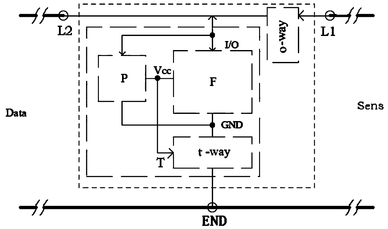
[0014] The calibration parameter storage of the vibrating wire sensor includes a two-core wire embedded structure, and its composition includes a storage unit for storing the calibration parameters of the connected vibrating wire sensor, such as figure 1 As shown in the dotted box, the storage unit is connected to the vibrating wire sensor through the measurement port Sens, and connected to the external measurement and control device through the communication port data.

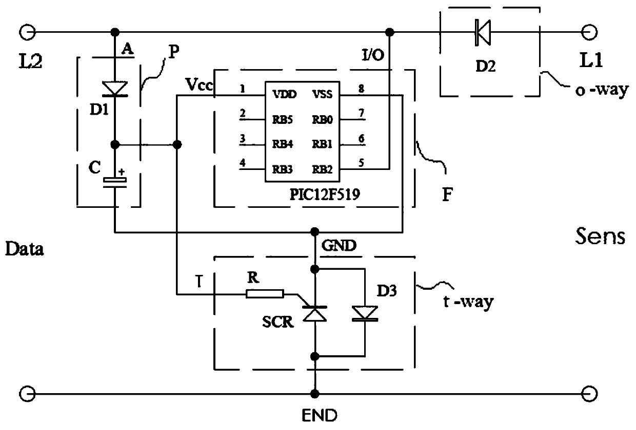
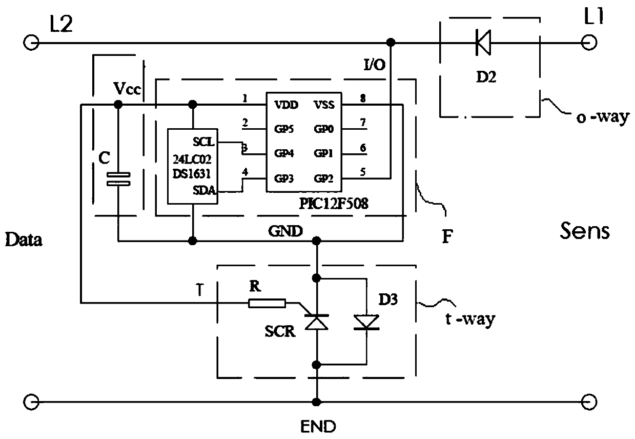
[0015] The storage unit includes a storage circuit F, a power supply circuit P and a bidirectional switch circuit t-way, wherein the storage circuit F can be formed by selecting a storage chip, or can be selected such as Figure 5 The memory chip DS2430A of the one-line bus system is ...


PUM


Abstract

The invention provides a two-core wire embedding structure for a storage package of calibration parameters of vibrating wire sensors. The two-core wire embedding structure is formed by comprising a storage unit for storing vibrating wire sensor calibration parameters of a measuring port and a communication port, and the storage unit is formed by comprising a storage circuit, a power circuit and atwo-way switching circuit; the measuring port is an access port for being connected with the vibrating wire sensor and obtaining a frequency transmitting signal, and is jointly composed of the accessend and the common end; and the communication port is the port connecting the storage unit and an external measurement and control device, an external lead of the I / O end of the storage circuit is theexternal end of the communication port, and the communication port is jointly composed of the external end and the common end. According to the technical scheme, each vibration wire sensor is bound and associated with corresponding calibration characteristic parameters, the simplest two-core wiring structure is realized, and meanwhile, the original technical advantage of long-distance stable signal transmission of the sensors is maintained.

Description

technical field [0001] This patent application relates to the connection structure for obtaining the sensing and transmitting signals of sensors, in particular to the connection structure for obtaining the sensing and transmitting signals of vibrating wire sensors. Background technique [0002] The vibrating wire sensor has simple structure, quasi-digital output signal, strong anti-interference ability, little temperature influence, long service life, and especially has two-core stable long-distance signal transmission characteristics unmatched by other sensors. It is widely used in various civil engineering fields. Among them, construction and quality monitoring such as bridges, tunnels, dams, pile foundations, railways, etc. are widely used to obtain frequency signals, and then convert them into pressure (KN), stress (MPa), strain (με), displacement ( mm) and other physical quantities. Due to various reasons such as product types, structures, and manufacturing processes, ...

Claims


Application Information

Patent Timeline
Patent Type & Authority Applications(China)
IPC IPC(8): G01D18/00
CPCG01D18/00
Inventor 杨毅
Owner 杨毅
Why Eureka
Try Eureka