A Quantitative Identification Method of Satellite Microvibration Sources Based on Sparse Blind Source Separation

A technology of blind source separation and quantitative identification, which is applied to pattern recognition in signals, character and pattern recognition, measurement devices, etc. Effective calculation, improved precision, and high accuracy

Active Publication Date: 2021-02-09
XI AN JIAOTONG UNIV
View PDF6 Cites 0 Cited by
  • Summary
  • Abstract
  • Description
  • Claims
  • Application Information

AI Technical Summary

Problems solved by technology

Moreover, the actual satellite structure is complex, and the main micro-vibration sources are rotating parts such as control moment gyroscopes and flywheels, resulting in many harmonic components of the vibration source signals and strong frequency band overlap between the vibration source signals, making the identification of micro-vibration source signals increasingly difficult. It also leads to the sum of the energy of each response signal at the observation point when each vibration source operates in divisions, and the energy of the mixed response signal at the observation point when each vibration source operates at the same time is not equal, making it difficult for the contribution represented by energy to accurately reflect the vibration source. True Contribution at Observatory

Method used


Image

  • A Quantitative Identification Method of Satellite Microvibration Sources Based on Sparse Blind Source Separation
  • A Quantitative Identification Method of Satellite Microvibration Sources Based on Sparse Blind Source Separation
  • A Quantitative Identification Method of Satellite Microvibration Sources Based on Sparse Blind Source Separation

Examples


Embodiment Construction

[0063] The present invention is described in detail below in conjunction with accompanying drawing and specific embodiment:

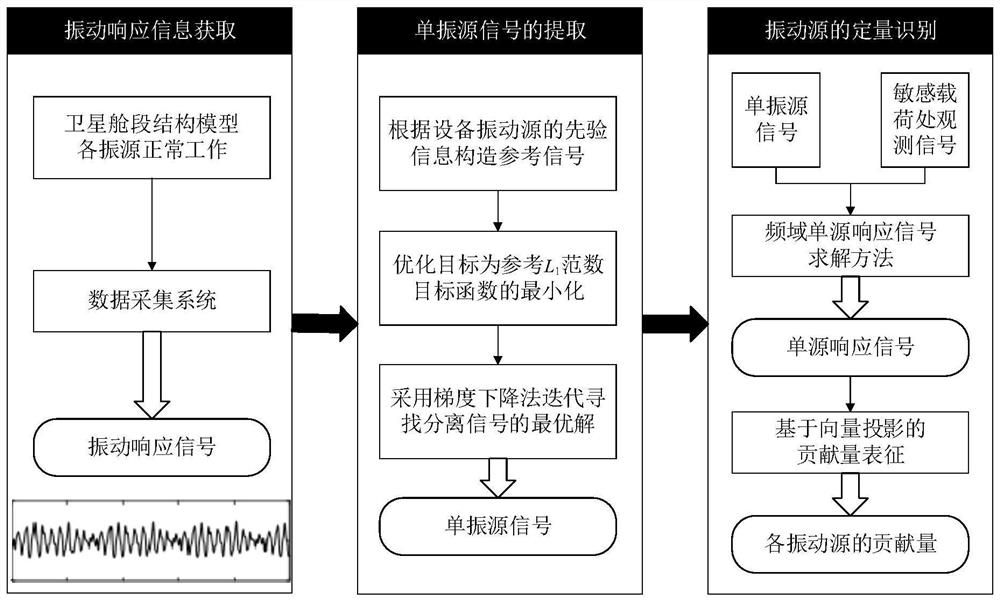
[0064] refer to figure 1 Shown is the flow chart of quantitative identification of satellite micro-vibration sources. The vibration sources of the satellite cabin structure model are working normally, and the vibration signals of sensitive loads and different positions on the model surface are collected to ensure that the number of observation signals is greater than the number of source signals; 1 Norm Construction Reference Sparse Blind Deconvolution Algorithm Reference L 1 The norm objective function constructs the reference signal according to the prior information of the vibration source, and uses the gradient descent method to iteratively optimize the reference L 1 Norm objective function, find the optimal solution of the separation signal y corresponding to the minimum objective function, and realize the extraction of single vibration source sig...


PUM


Abstract

The invention discloses a method for quantitative identification of satellite micro-vibration sources based on sparse blind source separation. First, acceleration sensors are arranged at sensitive loads of satellite cabin structural models and at different positions on the model surface to collect vibration signals of each vibration source during normal operation. Make sure that the number of observed signals is greater than the number of sources; then, using L 1 Norm Construction Reference Sparse Blind Deconvolution Algorithm Reference L 1 The norm objective function constructs the reference signal according to the prior information of the time-frequency domain characteristics of the vibration source, and uses the gradient descent method to iteratively optimize the objective function to find the optimal solution of the separated signal and realize the extraction of the single vibration source signal. Finally, the frequency-domain single-source response signal solution method is used to calculate the single-source response signal of each vibration source at the sensitive load; the contribution of each vibration source at the sensitive load is calculated using the vector projection-based contribution characterization method. The contribution evaluation index is an index for quantitative identification of satellite micro-vibration sources, which can provide a basis for micro-vibration suppression.

Description

technical field [0001] The invention relates to a method for quantitatively identifying vibration sources of mechanical equipment, in particular to a method for quantitatively identifying satellite micro-vibration sources based on sparse blind source separation. Background technique [0002] As key aerospace equipment, satellites play an important role in national military defense construction and national economic development. As the future development direction of satellites, high-resolution satellites have attracted widespread attention from all over the world. However, satellite micro-vibration severely restricts the improvement of satellite resolution and other performance. Therefore, quantitative identification of satellite micro-vibration sources and evaluation of the contribution of main vibration sources to sensitive loads can provide a basis and basis for satellite micro-vibration suppression work, which has significant significance. engineering application value ...

Claims


Application Information

Patent Timeline
Patent Type & Authority Patents(China)
IPC IPC(8): G06K9/00G01H17/00
CPCG01H17/00G06F2218/10G06F2218/02
Inventor 张周锁王欢宫腾罗欣
Owner XI AN JIAOTONG UNIV
Why Eureka
Try Eureka