Eureka AIR delivers breakthrough ideas for toughest innovation challenges, trusted by R&D personnel around the world.

Electric heating pad power cut-off device and method

A technology of cutting device and electric heating pad, which is applied to electric heating devices, ohmic resistance heating, electrical components, etc., can solve the problems of complicated and boring users, and achieve the effect of reducing production costs.

Inactive Publication Date: 2019-08-09
宋灿 +1
View PDF6 Cites 0 Cited by
  • Summary
  • Abstract
  • Description
  • Claims
  • Application Information

AI Technical Summary

Problems solved by technology

[0005] However, if the aforementioned electric heating pad is not used when the power is turned on by the user, the power supply needs to be turned off (off) to stop the power supply and save power, and it can also prevent fire hazards caused by overheating. If it is not used, especially when there is no one at home for a long time, there may be a danger of safety accidents such as fire alarms caused by overheating. Therefore, a power cut-off device is installed on the power conditioner so that it will automatically turn off after the set time has passed. Cut off the power, regardless of whether the user is using the mat or the user is not there, the power will be automatically cut off as long as the set time is reached, so as to reduce power waste or prevent fire caused by overheating when the user is not there. Accidents are dangerous, but when the set time is reached during use, the power will be automatically cut off and the power needs to be turned on again, and such situations will cause users to feel complicated and annoying

Method used


Image

  • Electric heating pad power cut-off device and method
  • Electric heating pad power cut-off device and method
  • Electric heating pad power cut-off device and method

Examples


Embodiment Construction

[0050] The configuration of the present invention will be described in detail below in conjunction with the accompanying drawings.

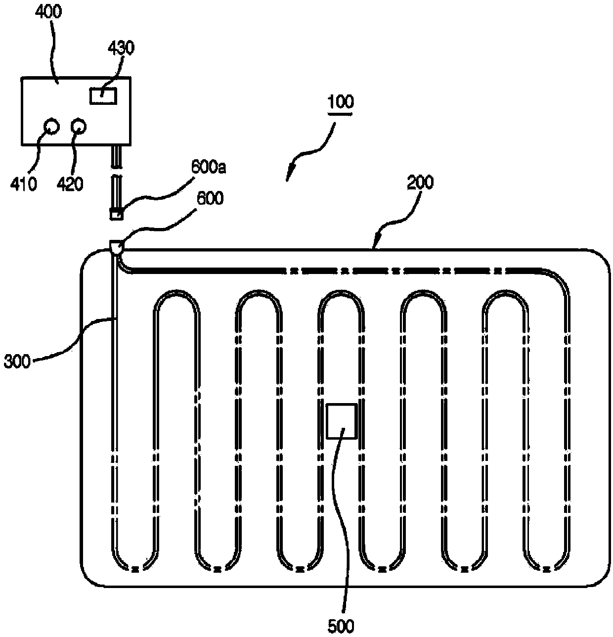
[0051] figure 2 It is an illustration showing the structure of a general heating pad. The heating pad 100 includes a mattress 200 with a size for a user to sit or lie on, a heating wire 300 buried inside the mattress, and a wire connected to the heating wire. In this state, the power regulator 400 and the sensing component 500 are turned on or off.

[0052] The mattress pad 200 includes a cushion part 210 having a predetermined thickness, and a cover part 220 placed on the upper and lower surfaces of the cushion part, and their outer peripheries can be decorated by tailoring.

[0053] At this time, the above-mentioned mattress can be made into various sizes such as single or double and extra large according to the purpose of use.

[0054] Moreover, the heating wire 300 is buried inside the mattress 200, and the end portions on both sides are e...


PUM


Abstract

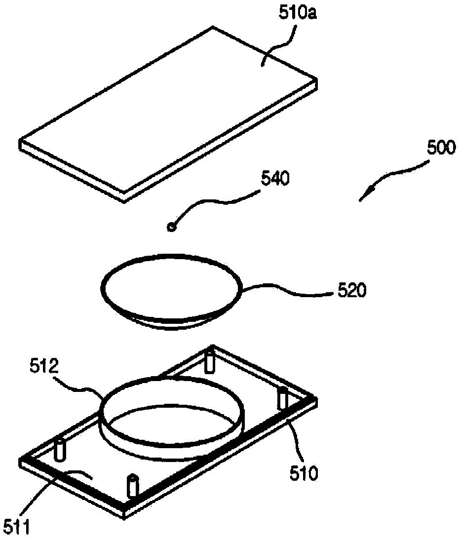
The invention relates to an electric heating pad power cut-off device and method. The electric heating pad is provided with an induction component. The induction component and an electric heating wireembedded in the mattress are separately embedded to enable initialization of the set time of a timing sensor by short circuit of the power supply. The induction component comprises a box body which is split and provided with a storage cavity; a current flow part which is arranged in the storage cavity of the box body and connected to the timing sensor by an electric wire; and current circulationballs which are arranged on the current flow part and freely and movably perform the short circuit function of the current. The current flow part comprises an aluminum plate having a circular shape and presenting to be curved downward from the outer peripheral edge to the center; an insulating member which is coated on the entire upper surface of the aluminum plate so as to cut off conduction of the current; and positive and negative copper wires which are coated in a snail-like shape on the upper surface of the insulating member from the center with a spacing at which the current circulationballs can be contacted.

Description

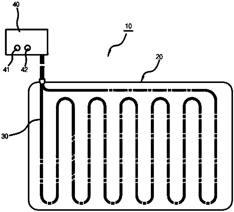
technical field [0001] The present invention relates to an electric heating pad, especially a power cut-off device and method of the electric heating pad, that is, if the mat (Mat) is not shaken within a certain period of time when the power is turned on, it is regarded as not in use The mat automatically cuts off the power. Background technique [0002] Generally speaking, the electric heating pad will bury the electric heating wires that emit heat after receiving the power supply at a certain distance inside the mat that is made into a predetermined size according to the purpose of use. The heating wire embedded in the mat heats up the mat, allowing the user to rest or sleep in a warm state. [0003] This existing heating pad (10) such as figure 1 As shown, it includes a mattress (20), an electric heating wire (30) embedded in the above-mentioned mat, a power regulator (40) that operates the on and off of the power supply under the state connected to the above-mentioned ...

Claims


Application Information

Patent Timeline
IPC IPC(8): H05B1/02H05B3/34
CPCH05B1/0202H05B1/0272H05B3/342
Inventor 宋灿林政大
Owner 宋灿
Why Eureka
Eureka Blog
Learn More