
LED light source control device and method, light source component and photoelectric pulse detection device

A technology of LED light source and control device, which is applied in the field of LED light source control device, light source component and photoelectric pulse detection device, can solve the problems of poor brightness uniformity, achieve uniform light output, and improve the effect of light output

Active Publication Date: 2019-08-09
SHENZHEN JPT OPTO ELECTRONICS CO LTD
View PDF7 Cites 1 Cited by
  • Summary
  • Abstract
  • Description
  • Claims
  • Application Information

AI Technical Summary

Problems solved by technology

Due to the inconsistency of the installation position, driving voltage or current, etc., the LED light source in the traditional technology has the problem of poor brightness uniformity.

Method used


Image

  • LED light source control device and method, light source component and photoelectric pulse detection device
  • LED light source control device and method, light source component and photoelectric pulse detection device
  • LED light source control device and method, light source component and photoelectric pulse detection device

Examples


Embodiment Construction

[0072] In order to make the purpose, technical solution and advantages of the present application clearer, the present application will be further described in detail through the following embodiments and in conjunction with the accompanying drawings. It should be understood that the specific embodiments described here are only used to explain the present application, not to limit the present application.

[0073] The serial numbers numbered for components in this document, such as "first", "second", etc., are only used to distinguish the described objects and do not have any sequence or technical meaning. The "connection" and "connection" mentioned in this application all include direct and indirect connection (connection) unless otherwise specified. In the description of this application, it should be understood that the terms "upper", "lower", "front", "rear", "left", "right", "vertical", "horizontal", "top", The orientation or positional relationship indicated by "bottom"...


PUM


Abstract

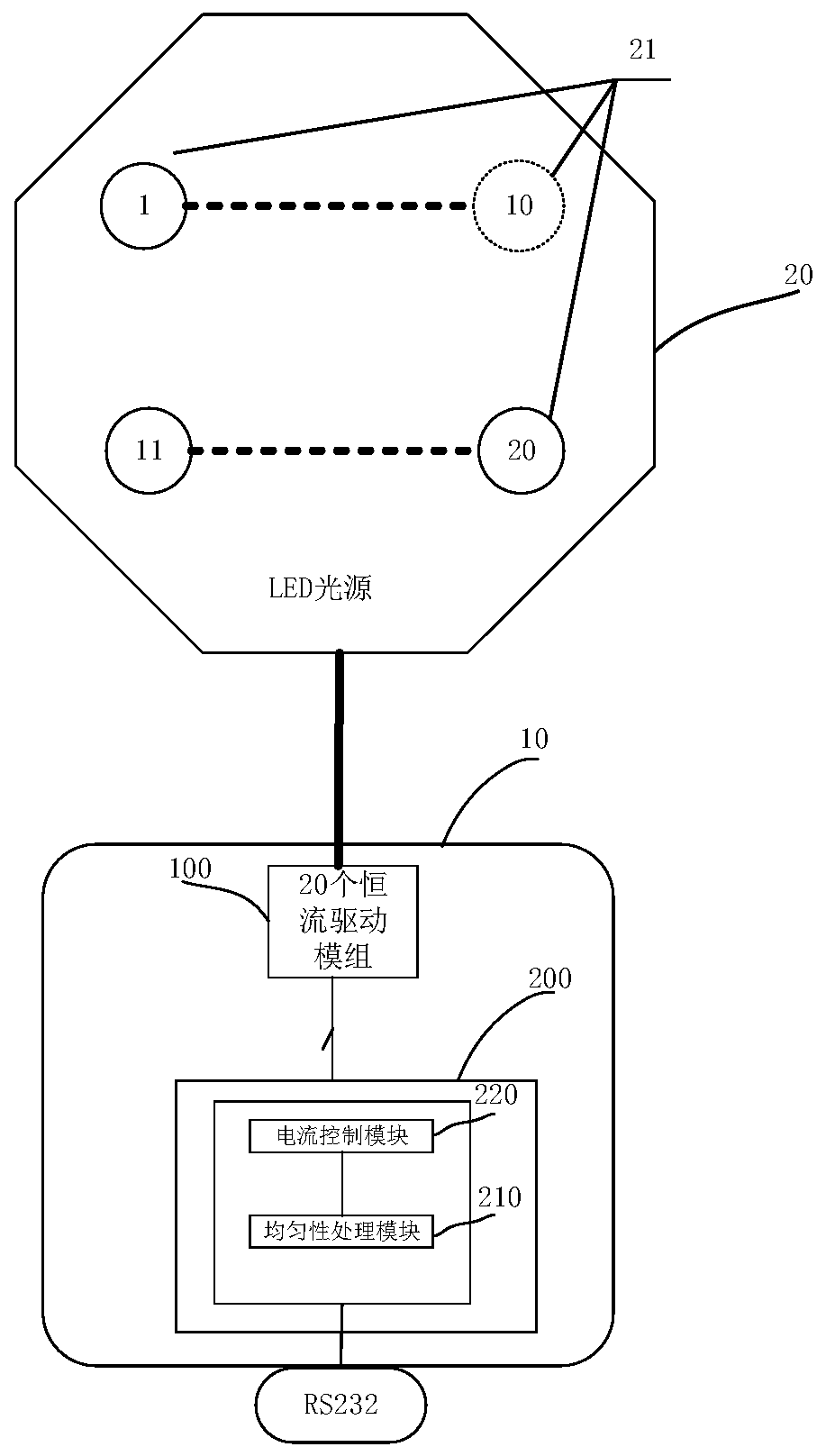
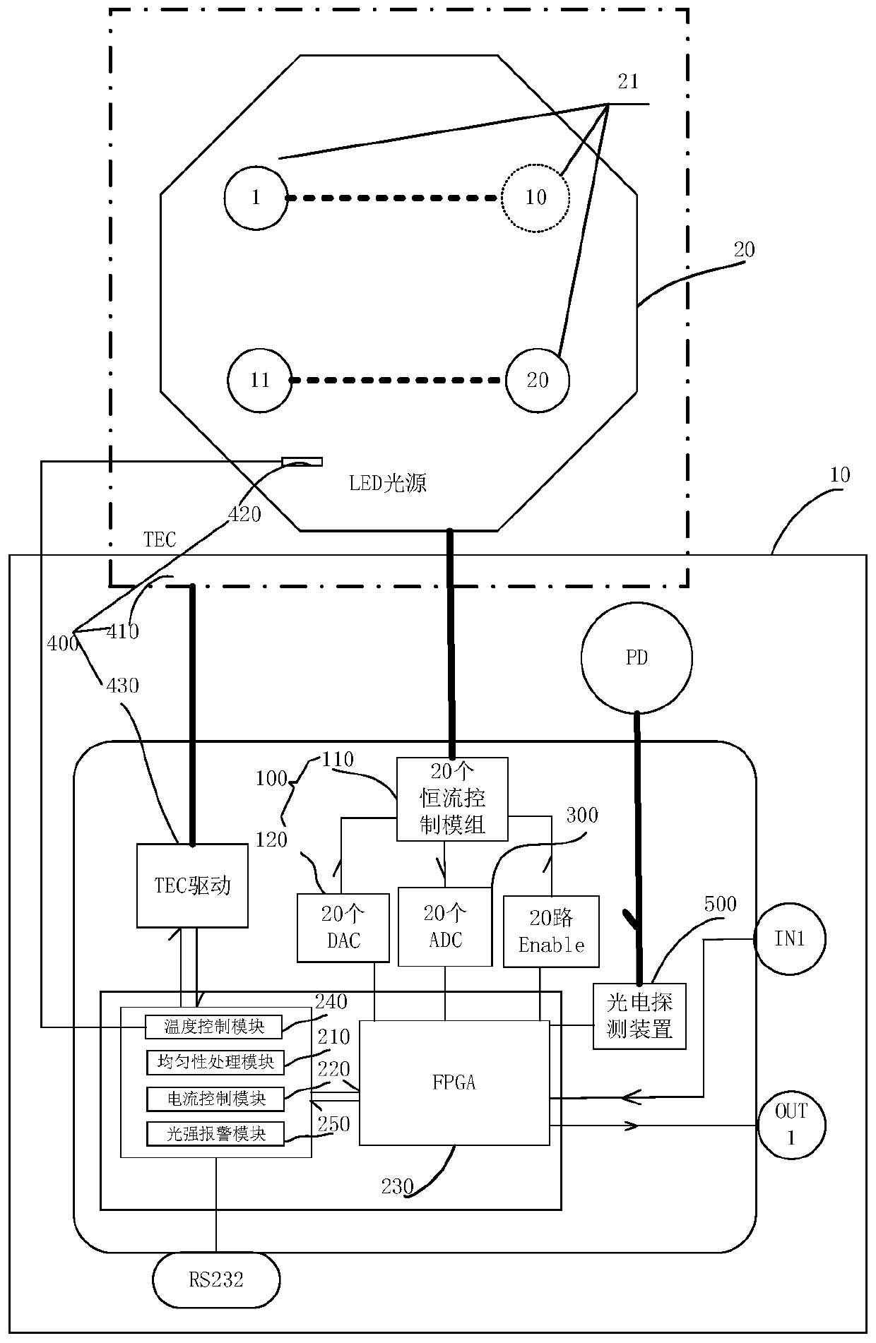
The invention relates to an LED light source control device and method, a light source assembly and a photoelectric pulse detection device. The LED light source control device is used for controllingan LED light source. The LED light source comprises multiple LED lamps. The LED light source control device comprises multiple constant current drive modules and a control module. Multiple constant current drive modules are electrically connected with multiple LED lamps and used for driving multiple LED lamps. The control module comprises a uniformity processing module and a current control module. The uniformity processing module is electrically connected with the current control module. The current control module is electrically connected with multiple constant current drive modules. The uniformity processing module is used for receiving the uniformity parameters of the LED light source and determining the drive current adjustment scheme for multiple LED lamps according to the uniformityparameters. The current control module is used for adjusting the drive current of multiple LED lamps according to the drive current adjustment scheme. The LED light source control device can improvethe uniformity of the LED light source.

Description

technical field [0001] The present application relates to the field of LEDs, in particular to an LED light source control device, method, light source assembly and photoelectric pulse detection device. Background technique [0002] LED (Light Emitting Diode, light-emitting diode) is a semiconductor electronic component that can convert electrical energy into light energy. With the continuous advancement of technology, LEDs have been widely used in monitors, televisions, lighting decoration and lighting. [0003] The LED light source generally includes a plurality of LED lamps. Brightness uniformity is an important indicator of LED light sources. Due to the inconsistency of installation position, driving voltage or current, etc., the LED light source in the traditional technology has the problem of poor brightness uniformity. Contents of the invention [0004] Based on this, it is necessary to provide an LED light source control device, a method, a light source component...

Claims


Application Information

Patent Timeline
IPC IPC(8): H05B33/08G05D23/19H05B44/00
CPCG05D23/19H05B45/14H05B45/00H05B45/50H05B45/10Y02B20/30
Inventor 唐明陈建强欧阳威张小东
Owner SHENZHEN JPT OPTO ELECTRONICS CO LTD
Learn More