
Anti-scrap abrasion numerical control machine tool spindle brake device

A technology of CNC machine tools and spindles, which is applied to drive devices, metal processing mechanical parts, maintenance and safety accessories, etc. The effect of preventing debris from entering the brake chamber

Inactive Publication Date: 2019-08-13
CHONGQING VOCATIONAL INST OF ENG
View PDF9 Cites 2 Cited by
  • Summary
  • Abstract
  • Description
  • Claims
  • Application Information

AI Technical Summary

Problems solved by technology

[0003] chip processing, and the spindle rotation is driven by the spindle motor. High-speed rotating chips generally process revolving parts, such as cylinders, cones and curved surface revolving parts. Most machine tools rely on magnetic force to stop the spindle. , but because the machine tool will generate waste chips when it is working, and the magnetic brake disc and brake clamping block will absorb metal waste on the surface after the magnetic force is generated, and the waste chips between the magnetic brake disc and brake clamping block will make it The fit is not tight enough, and the long-term accumulation of brake disc wear is serious. The application number 201720074439.8 announced a kind of anti-waste chip wear CNC machine tool spindle brake device, including the machine tool body and the spindle body. The spindle body is movably installed inside the machine tool body. The surface of the main body is sleeved with a bearing, and the surface of the main shaft body is fixedly connected with a brake disc located on the right side of the bearing. The brake disc is movably connected inside the machine tool body. The end of the brake disc away from the bearing runs through the machine tool body and extends to the right side of the machine tool body. , the inside of the machine tool body is fixedly connected with the placement blocks located on the top of the main shaft body and on both sides of the brake disc. Although there is some improvement on the original basis, a single brake structure is used as a whole for braking. After a long time of use, it will cause The overall heat will affect the braking effect, so it may affect the processing accuracy and cause losses to users.

Method used


Image

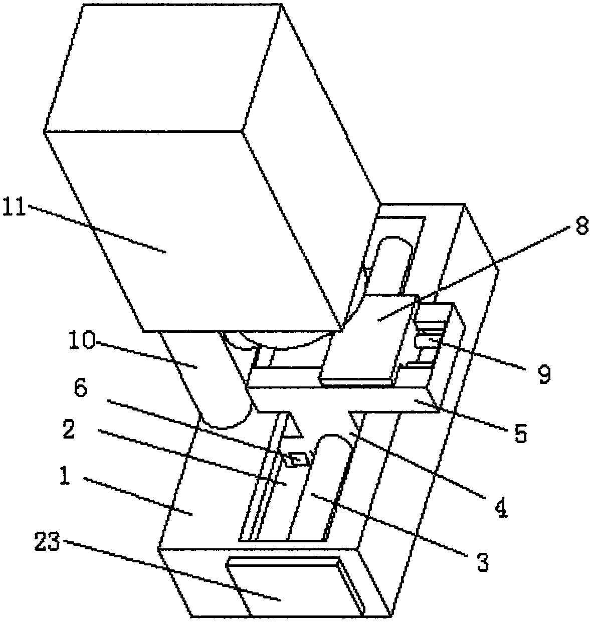
  • Anti-scrap abrasion numerical control machine tool spindle brake device
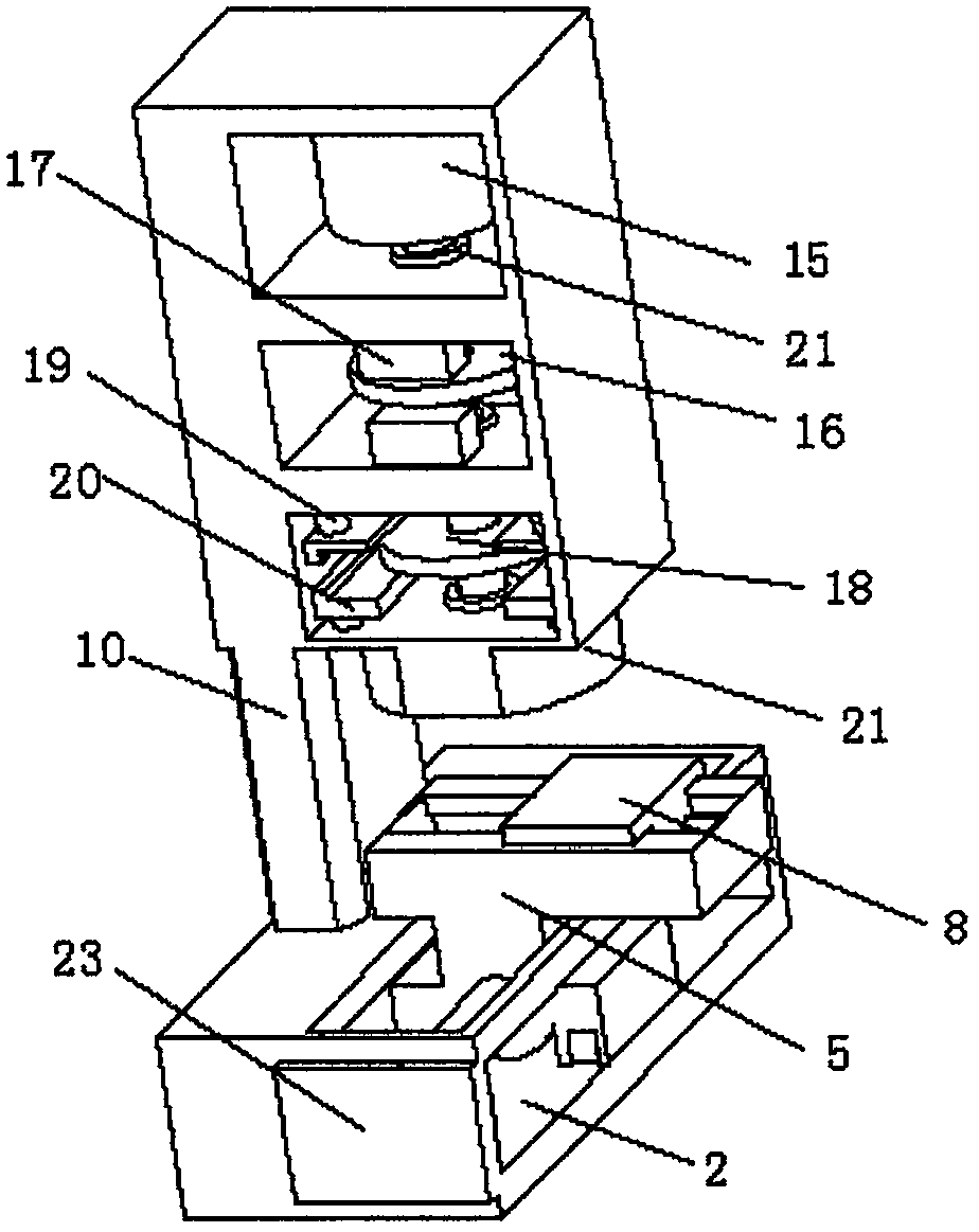
  • Anti-scrap abrasion numerical control machine tool spindle brake device
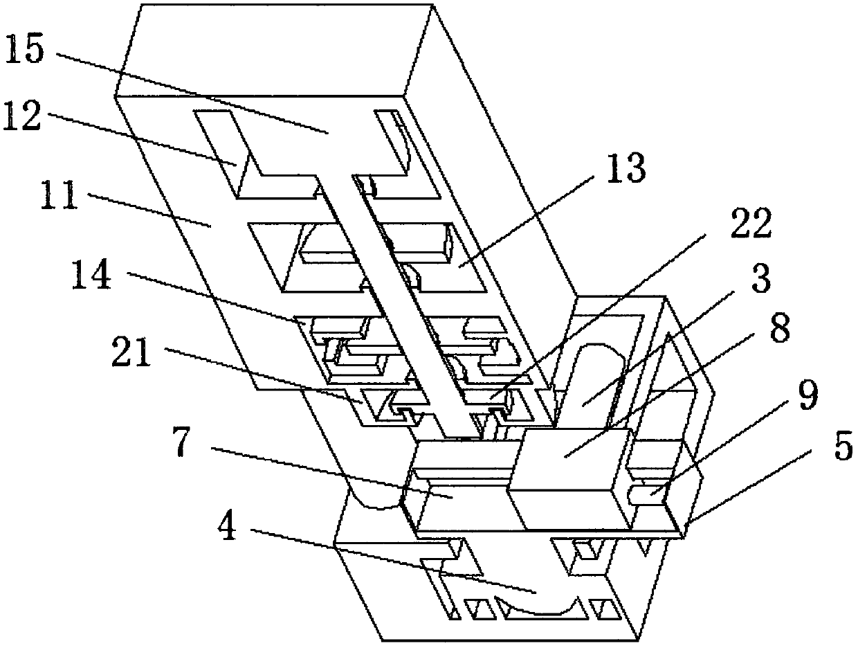
  • Anti-scrap abrasion numerical control machine tool spindle brake device

Examples


Embodiment Construction

[0020] The following will clearly and completely describe the technical solutions in the embodiments of the present invention with reference to the accompanying drawings in the embodiments of the present invention. Obviously, the described embodiments are only some, not all, embodiments of the present invention. Based on the embodiments of the present invention, all other embodiments obtained by persons of ordinary skill in the art without making creative efforts belong to the protection scope of the present invention.

[0021] see Figure 1-3 , the present invention provides a technical solution: an anti-waste chip wear CNC machine tool spindle braking device, including a base 1, the surface of the base 1 is provided with a first chute 2, the first chute 2 is provided with a screw 3, The screw mandrel 3 is rotatably connected with a linear motor 4, the side of the linear motor 4 is provided with a mounting frame 5, the top of the mounting frame 5 is provided with a second chu...


PUM


Abstract

The invention discloses an anti-scrap abrasion numerical control machine tool spindle brake device. The device includes a pedestal; the surface of the pedestal is provided with a first slide groove; ascrew rod is arranged in the first slide groove; the screw rod is rotatably connected to a linear motor; the side surface of the linear motor is provided with an installation rack; the top end of theinstallation rack is provided with a second slide groove; the second slide groove is slidingly connected to a fixing device; the surface of the pedestal is connected to a power device; the side surface of the pedestal is provided with a control switch block; and the output end of the control switch block is electrically connected to the input end of the linear motor. Through brake structures at the internals of a first brake cabin and a second brake cabin, brake operation can be performed on a spindle, and brake effects can be guaranteed; and through the structural design of sealing rings andsealing gaskets, scraps can be effectively prevented from entering the brake cabins, so that the operation stability of internal equipment of the brake cabins can be guaranteed.

Description

technical field [0001] The invention relates to the technical field of machinery, in particular to a brake device for preventing the wear and tear of waste debris on the spindle of a CNC machine tool. Background technique [0002] Generally, multi-axis CNC machine tools can not only process chips at high speed of the spindle, but also realize the machining of parts when the spindle is stopped. [0003] chip processing, and the spindle rotation is driven by the spindle motor. High-speed rotating chips generally process revolving parts, such as cylinders, cones and curved surface revolving parts. Most machine tools rely on magnetic force to stop the spindle. , but because the machine tool will generate waste chips when it is working, and the magnetic brake disc and brake clamping block will absorb metal waste on the surface after the magnetic force is generated, and the waste chips between the magnetic brake disc and brake clamping block will make it The fit is not tight enou...

Claims


Application Information

Patent Timeline
Patent Type & Authority Applications(China)
IPC IPC(8): B23Q5/20B23Q11/08
CPCB23Q5/20B23Q11/0883
Inventor 刘玉玺
Owner CHONGQING VOCATIONAL INST OF ENG
Learn More