Combined valve

A combined valve and valve stem technology, applied to multi-way valves, valve devices, engine components, etc., can solve problems affecting fluid pressure, piston and cylinder end cover wear, and different working time sequences to ensure operational safety and stability, avoiding collision wear, reasonable and practical structure

Inactive Publication Date: 2013-08-21
皇甫美蓉
View PDF6 Cites 10 Cited by
  • Summary
  • Abstract
  • Description
  • Claims
  • Application Information

AI Technical Summary

Problems solved by technology

Not only can it produce a lot of collision noise, but it will inevitably cause serious wear to the piston and cylinder end cover
After using for a period of time, it will inevitably cause certain damage to the piston and the end cover of the cylinder body; the higher the pressure, the faster the speed, the shorter the service life of the piston cylinder, and at the same time, it is easy for each cylinder to affect each other
[0003] Although the inventor discloses an improved combination valve in a multi-functional valve and its combination valve document of patent application number 201110398070.3, to prevent the piston from impacting the cylinder end cover, thereby prolonging the service life of the piston cylinder, in Practice shows that there are still some deficiencies in some applications. For example, the working time sequence of the two cylinders is different, which will cause the fluid pressure in one cylinder to affect the fluid pressure in the other cylinder. Interference, so that the cylinder pistons controlled by each reversing control valve cannot work well in sequence, and further improvement is needed

Method used


Image

  • Combined valve
  • Combined valve
  • Combined valve

Examples


Embodiment Construction

[0027] The present invention will be further described in detail below in conjunction with the accompanying drawings and embodiments.

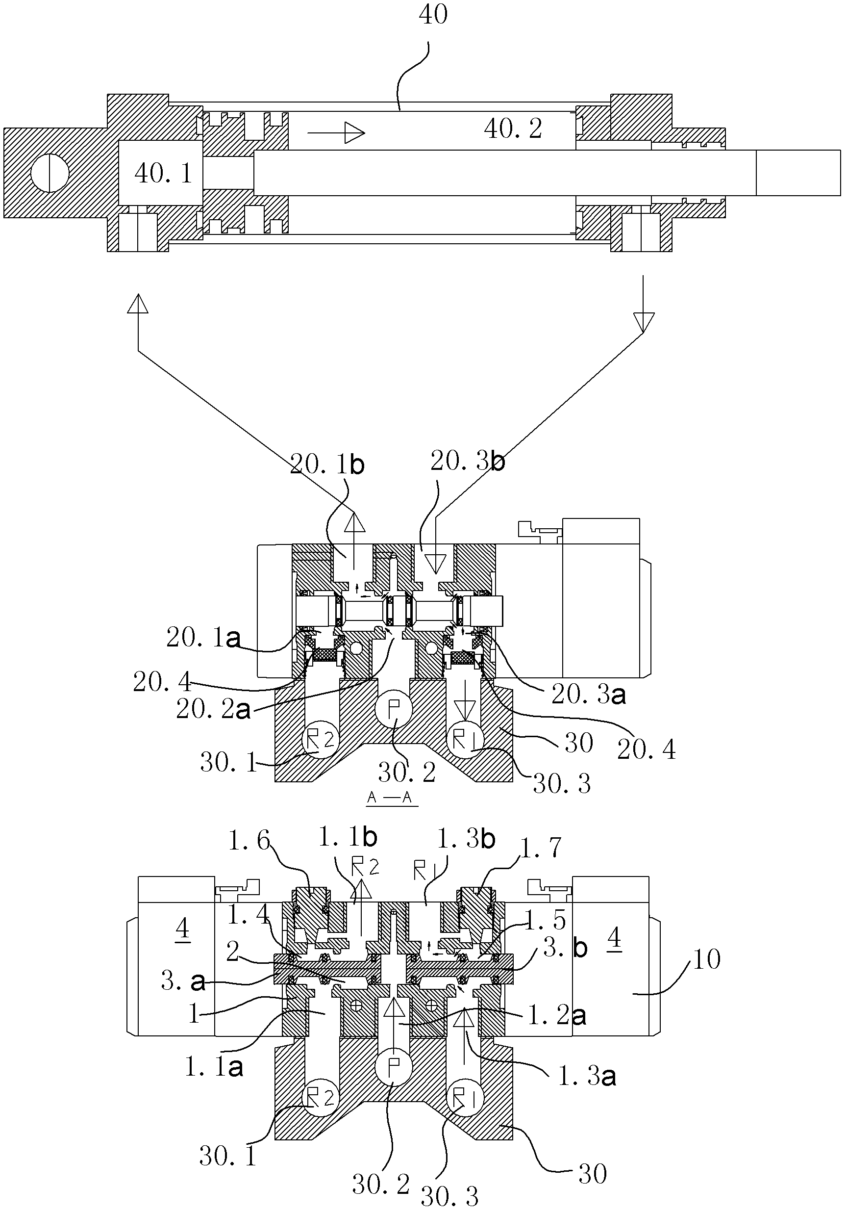
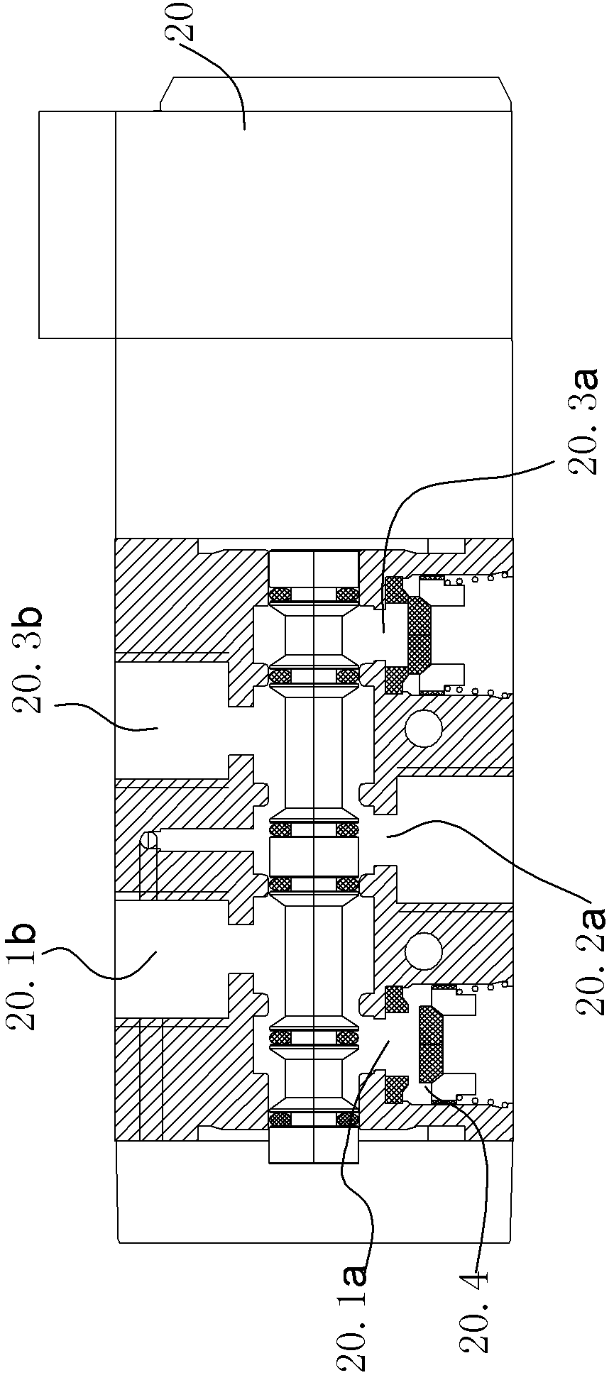
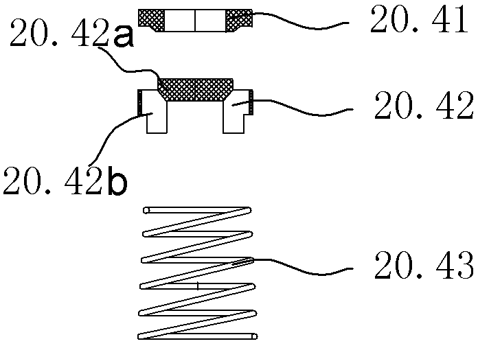
[0028] Such as figure 1 , 7 As shown, a combined valve or valve island, which includes a multi-function valve 10, three steering reversing valves 20 and a manifold 30; the left port 20.1b and right port 20.3b on one side of the steering reversing valve 20 The left cavity 40.1 and the right cavity 40.2 of the piston cylinder 40 are respectively connected, and the left return port 20.1a, the middle inlet 20.2a and the right return port 20.3a on the other side of the steering reversing valve 20 are respectively connected to the left flow channel 30.1 of the manifold 30 , the middle flow channel 30.2 and the right flow channel 30.3, and a check valve 20.4 is respectively arranged on the channel of the left backflow port 20.1a and the right backflow port 20.3a of the steering reversing valve. In this embodiment example, the check valve 20.4 is Se...


PUM


Abstract

The invention relates to a combined valve. The combined valve comprises a multifunctional valve, a confluence plate and at least one operation reversing valve, wherein a left opening and a right opening at one side surface of one operation reversing valve are respectively connected to a left cavity and a right cavity of a piston cylinder; a left reflux opening, a middle inlet and a right reflux opening at the other side surface of the operation reversing valve are respectively connected to a left flow channel, a middle flow channel and a right flow channel of the confluence plate; the channels of the left reflux opening and the right reflux opening of the operation reversing valve are respectively provided with a one-way valve; the left reflux opening and the right reflux opening are corresponding connected to a left flow channel and a right flow channel of the confluence plate through respective throttle valves; and the left inlet and right inlet of the multifunctional valve are respectively and correspondingly communicated with a left outlet and a right outlet through respective throttle valves. The combined valve avoids mutual influence among cylinders and collision abrasion to a piston and a cylinder end cover when the piston moves rapidly, prolongs the service life of the piston cylinder efficiently, and guarantees operation safety and stability of the piston cylinder.

Description

technical field [0001] The invention relates to the technical field of buffer valves and related valve groups. Background technique [0002] When the piston cylinder works at high speed or high pressure, the movement speed of the piston rod and the piston is very fast. In this way, when the piston quickly moves to the two limit positions of the front end and the rear end of the cylinder body, the piston and the end cover of the cylinder body will inevitably be closed. Collision. Not only can it produce a lot of collision noise, but it will inevitably cause serious wear and tear on the piston and the end cover of the cylinder block. After using for a period of time, certain damages will inevitably be caused to the piston and the cylinder end cap; the higher the pressure, the faster the speed, the shorter the service life of the piston cylinder, and it is also easy for each cylinder to affect each other. [0003] Although the inventor discloses an improved combination valve ...

Claims


Application Information

Patent Timeline
Patent Type & Authority Applications(China)
IPC IPC(8): F16K11/10
Inventor 皇甫岳伟
Owner 皇甫美蓉
Why Eureka
Try Eureka