Diversion mechanism

A technology of deflector mechanism and deflector plate, which is applied in the direction of metal processing machinery parts, metal processing equipment, maintenance and safety accessories, etc., and can solve the problems of excessive water flow, splashing, etc.

Active Publication Date: 2020-05-08
CHONGQING HONGGANG CNC MACHINE TOOL
View PDF10 Cites 0 Cited by
  • Summary
  • Abstract
  • Description
  • Claims
  • Application Information

AI Technical Summary

Problems solved by technology

[0003] The purpose of the present invention is to provide a flow guide mechanism to solve the technical problem of splashing when the water flow velocity is too fast

Method used


Image

  • Diversion mechanism
  • Diversion mechanism
  • Diversion mechanism

Examples


Embodiment 1

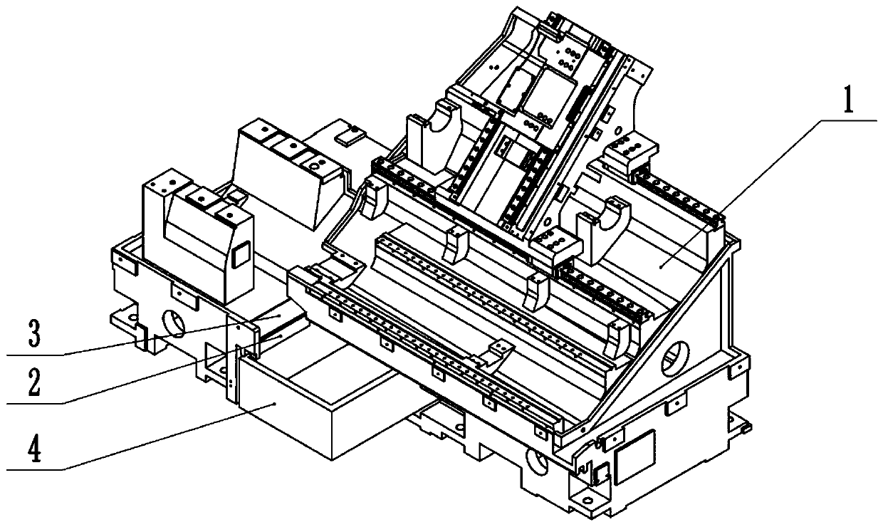
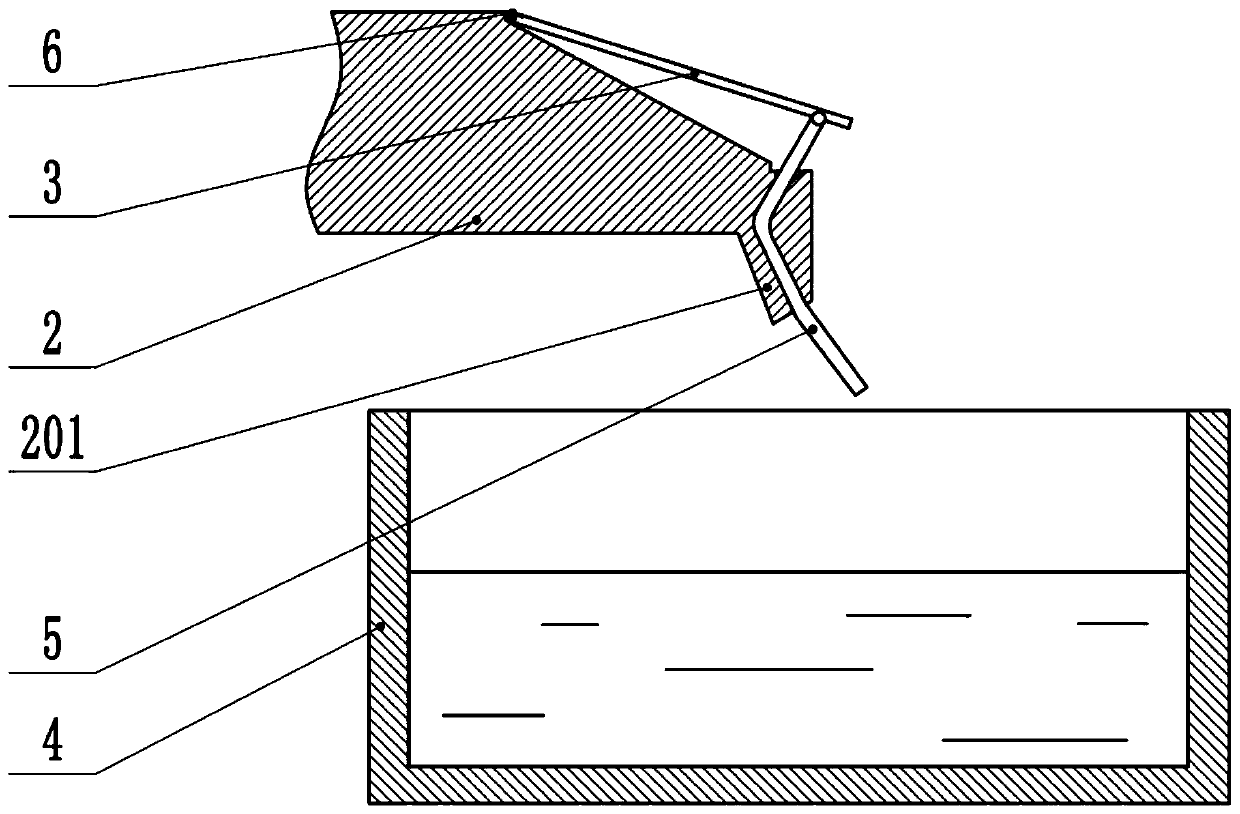
[0028] as attached figure 1 with attached figure 2 As shown, the guide mechanism includes a lathe 1 and a water tank 4. The diversion plate 2 is fixedly connected to the lathe 1 . The water tank 4 is horizontally slidably connected to the bottom of the lathe 1 . The diversion plate 2 is obliquely arranged on the top of the water tank 4, the inclination angle of the diversion plate 2 top surface is 120°, and the end of the diversion plate 2 away from the water tank 4 is the lowest end. The top surface of the diversion plate 2 is hinged with a diversion plate 3, the length of the diversion plate 3 along the inclined direction of the diversion plate 2 is greater than the length of the corresponding diversion plate 2, and a compression spring is fixedly connected between the top surface of the diversion plate 2 and the bottom surface of the diversion plate 3 . A rubber plate 5 is hinged at one end of the bottom surface of the deflector 3 away from the hinge of the deflector 3...

Embodiment 2

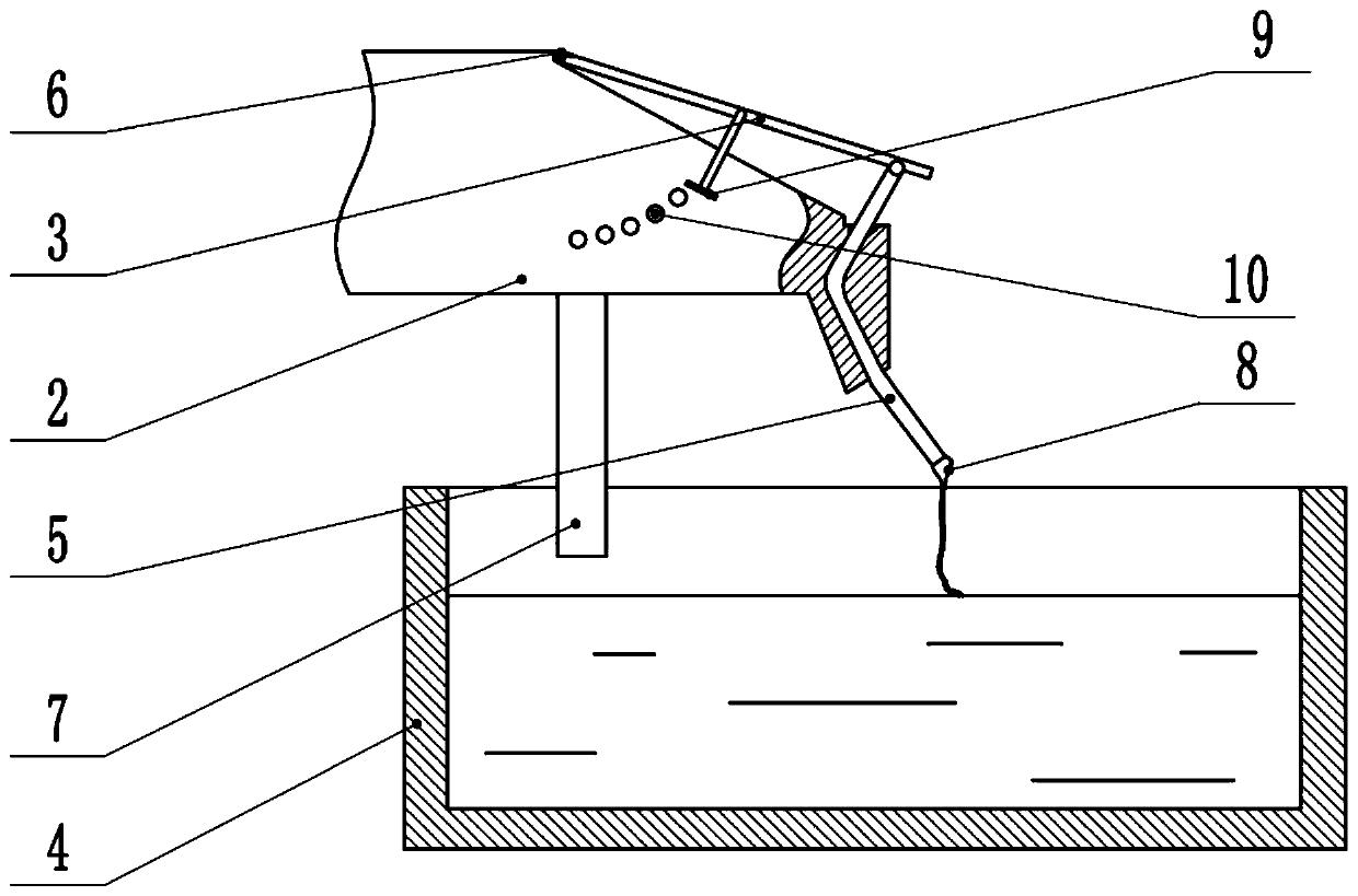
[0031] as attached image 3 As shown, the difference from Embodiment 1 is that the bottom surface of the drain plate 2 is also provided with a splash guard 7, the splash guard 7 and the drain plate 2 are integrally formed, and the bottom end of the splash guard 7 extends vertically downward , and the height of the bottom end of the splash guard 7 is less than the height of the top of the side wall of the water tank 4 . And the end of the rubber plate 5 away from the deflector 3 includes a layer of gauze 8, the height of the gauze 8 on the top surface of the deflector 3 is 3mm higher than the top surface of the deflector 3, and the end of the gauze 8 away from the deflector 3 extends out A piece of gauze 8, and extends to the liquid surface of water tank 4. The side wall of deflector 3 is threadedly connected to the strut, the axial direction of the strut is perpendicular to the bottom surface of deflector 3, the end of the strut away from deflector 3 extends to the side wall ...


PUM


Abstract

The invention relates to the technical field of machine tool machining and discloses a flow guide mechanism. The flow guide mechanism comprises a drainage plate and a water tank. The drainage plate isarranged above the water tank. The top surface of the drainage plate comprises an inclined drainage surface. The bottom surface of the drainage plate is provided with a bending part bent outwards. The drainage surface is provided with a through hole penetrating through the bending part in a communicating mode. A flow guide plate is hinged to the top end of the drainage surface. A torsion spring is arranged at the hinged position between the flow guide plate and the drainage plate. A flexible plate is further hinged to the end, far away from the torsion spring, of the flow guide plate. The end, far away from the flow guide plate, of the flexible plate is slidably connected to an inner cavity of the through hole and extends out of the through hole. The flow guide mechanism is provided by the invention for solving the technical problem that water flows too fast and is splashed.

Description

technical field [0001] The invention belongs to the technical field of machine tool processing. Background technique [0002] CNC machine tools can perform operations such as cutting and milling on processed metal workpieces, and are one of the processing equipment widely used in the machinery industry. During the machining process, a large amount of coolant needs to be sprayed to cool down the workpiece and cutting tool. Machine tools in the prior art usually have a return flow design, so that the coolant flows back into the water tank for recycling. During the coolant return process, when the coolant flow is too large, the coolant falling into the water tank will cause the water tank to stir up larger droplets, causing pollution to the environment around the machine tool. Contents of the invention [0003] The purpose of the present invention is to provide a flow guide mechanism to solve the technical problem of splashing when the water flow is too fast. [0004] In o...

Claims


Application Information

Patent Timeline
Patent Type & Authority Patents(China)
IPC IPC(8): B23Q11/10
CPCB23Q11/10
Inventor 汪传宏
Owner CHONGQING HONGGANG CNC MACHINE TOOL
Why Eureka
Try Eureka