Die-cut plate loading device of die cutting machine and application method thereof
A die-cutting board and die-cutting machine technology, applied in transportation and packaging, loading/unloading, metal processing, etc., can solve the problems of troublesome replacement process, low work efficiency, occupying space, etc., to facilitate maintenance and installation, and improve space. The effect of utilization
- Summary
- Abstract
- Description
- Claims
- Application Information
AI Technical Summary
Problems solved by technology
Method used
Image

Examples
Embodiment Construction
[0045] The present invention will be described in further detail below in conjunction with the accompanying drawings.
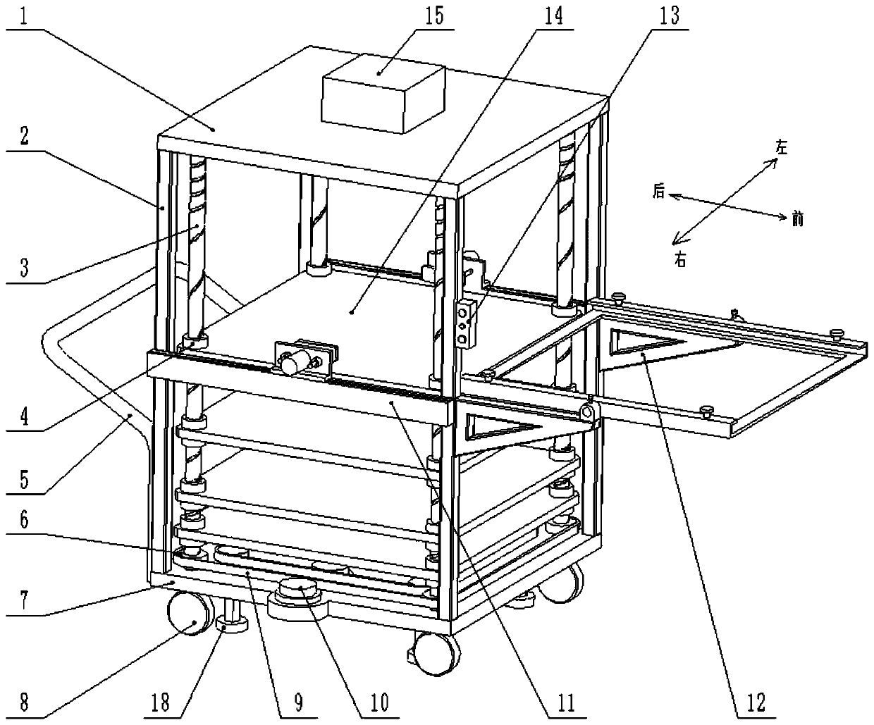
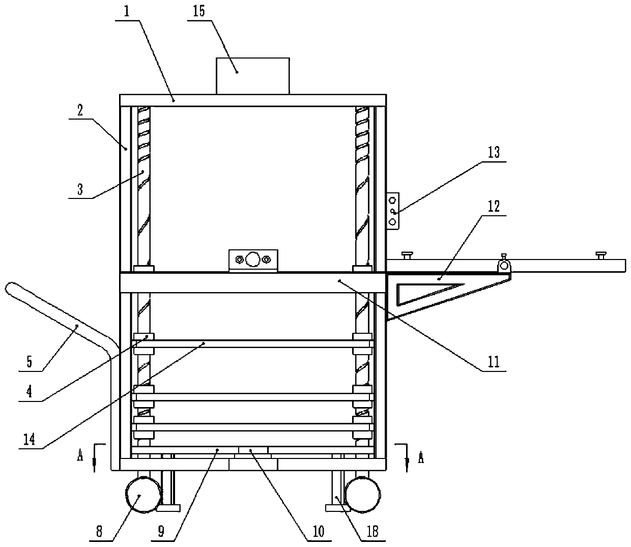
[0046] A die-cutting plate loading device for a die-cutting machine includes a storage rack, the storage rack includes a top plate 1, a bottom plate 7, and a column 2, and the top plate 1 and the bottom plate 7 are fixedly connected by four-corner columns 2.
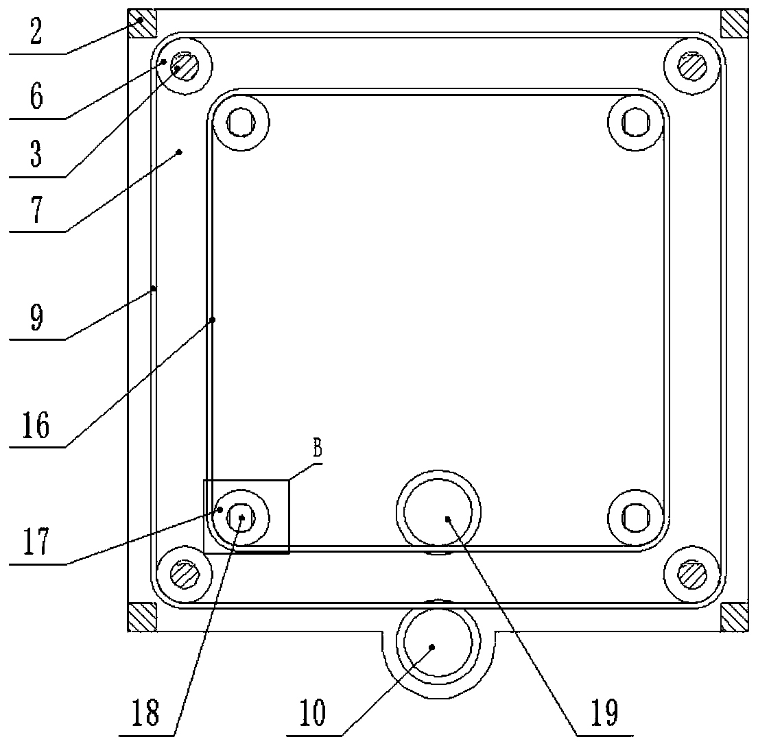
[0047]The four corners of the bottom plate 7 are provided with rectangular holes 701 , and the lifting base 18 is inserted into the rectangular holes 701 . Lifting seat 18 includes threaded column 1801 and support disc 1803, and the outer periphery of threaded column 1801 is provided with thread, and threaded column 1801 is provided with two positioning surfaces 1802 arranged in parallel, and the distance between two positioning surfaces 1802 is slightly smaller than the rectangular hole The width of 701, lifting seat 18 can not rotate in rectangular hole 701, and lifting seat 18 can only move up and do...
PUM
 Abstract
Description
Claims
Application Information
 - R&D
- Intellectual Property
- Life Sciences
- Materials
- Tech Scout
- Unparalleled Data Quality
- Higher Quality Content
- 60% Fewer Hallucinations
Browse by: Latest US Patents, China's latest patents, Technical Efficacy Thesaurus, Application Domain, Technology Topic, Popular Technical Reports.
© 2025 PatSnap. All rights reserved.Legal|Privacy policy|Modern Slavery Act Transparency Statement|Sitemap|About US| Contact US: help@patsnap.com