
Bridge temporary support device and installation method thereof

A technology of temporary support and installation method, which is applied in the direction of bridges, bridge construction, erection/assembly of bridges, etc., and can solve the problems of high cost of sulfur mortar temporary supports, impossibility of turnover, and difficult unloading of temporary sand box supports.

Pending Publication Date: 2019-08-13
CCCC SHANGHAI DREDGING
View PDF0 Cites 7 Cited by
  • Summary
  • Abstract
  • Description
  • Claims
  • Application Information

AI Technical Summary

Problems solved by technology

[0003] The design and construction of bridge temporary support devices is an important link in the erection of simply supported and then continuous girder bridges. At present, temporary support devices are usually used in construction, including sand box temporary supports or sulfur mortar temporary supports, etc. Temporary supports for sand boxes are not easy Unloading, difficult to control the height of the support, and the cost of the sulfur mortar temporary support is high, difficult to process, cannot be used for turnover, and the environment is polluted

Method used


Image

  • Bridge temporary support device and installation method thereof
  • Bridge temporary support device and installation method thereof
  • Bridge temporary support device and installation method thereof

Examples


Embodiment Construction

[0038] The specific implementation manner of the present invention will be described in more detail below with reference to schematic diagrams. The advantages and features of the present invention will be more apparent from the following description. It should be noted that all the drawings are in a very simplified form and use imprecise scales, and are only used to facilitate and clearly assist the purpose of illustrating the embodiments of the present invention.

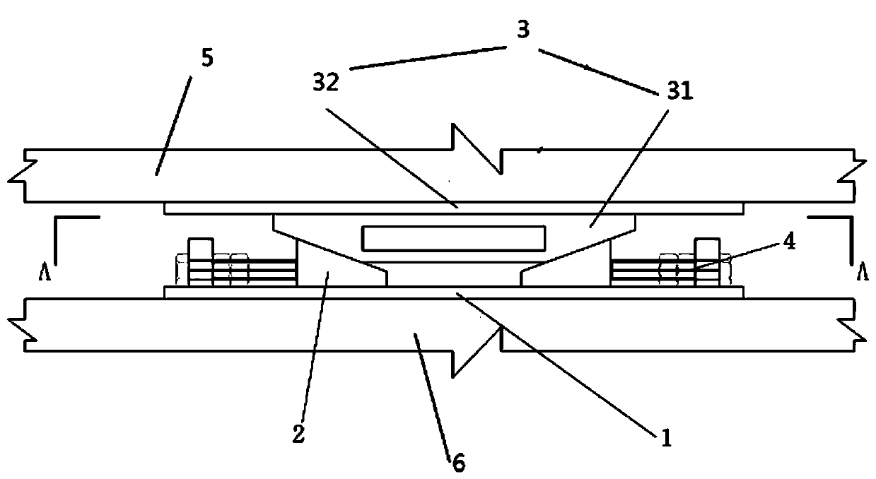
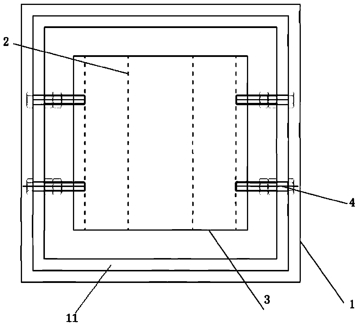
[0039] like figure 1 and figure 2 As shown, the present embodiment provides a bridge temporary support device for carrying a beam body 5, the beam body includes a T beam, a box girder or a plate girder, and the weight of the beam body can be controlled between 100KN-4000KN That is, the bearing capacity of the bridge temporary support device may be 100KN-4000KN.

[0040] The bridge temporary support device includes a support base plate 1, two sets of limit modules and a bearing module 3. The support base plate 1...


PUM


Abstract

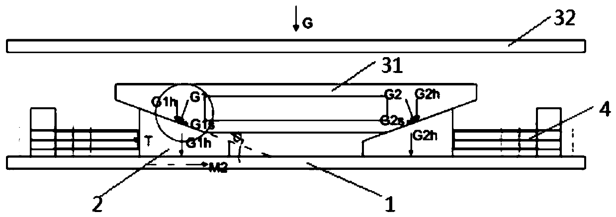
The invention provides a bridge temporary support device and an installation method thereof. The bridge temporary support device comprises a supporting seat bottom plate, two groups of limiting modules and a bearing module, wherein the two groups of the limiting modules are symmetrically arranged on the supporting seat bottom plate, the bearing module is arranged on the limiting modules, and the two groups of the limiting modules can move towards each other or away from each other on the surface of the supporting seat bottom plate to enable the vertical height between the bearing module and the supporting seat bottom plate to be increased or decreased. When a bridge body is supported, the temporary support device is installed according to the installation method, and the two groups of thelimiting modules move towards each other to enable the vertical height between the bearing module and the supporting seat bottom plate to be increased to a preset height. When unloading is carried out, the two groups of the limiting modules move away from each other to enable the height from the bearing module to the supporting seat bottom plate to be decreased to dismantle the temporary support device. The bridge temporary support device has the advantages that the construction cost is low, the installation is simple, the support structure is stable, and recycling can be achieved.

Description

technical field [0001] The invention relates to the technical field of continuous girder bridge erection, in particular to a bridge temporary support device and an installation method thereof. Background technique [0002] With the rapid development of bridge construction, a new type of girder bridge structure has emerged in China in recent years—simply supported first and then continuous girder bridge. The advantages of convenience and short construction period have played an important role in bridge construction. [0003] The design and construction of bridge temporary support devices is an important link in the erection of simply supported and then continuous girder bridges. At present, temporary support devices are usually used in construction, including sand box temporary supports or sulfur mortar temporary supports, etc. Temporary supports for sand boxes are not easy Unloading, the height control of the support is difficult, and the cost of the temporary support of su...

Claims


Application Information

Patent Timeline
IPC IPC(8): E01D21/00
CPCE01D21/00
Inventor 徐荣华蒋彪容之攀易磊张军杨鲁齐徐震胡洲曾涛周稚钧黄智斌
Owner CCCC SHANGHAI DREDGING
Learn More