Flow collecting pipe assembly and heat exchanger

A collecting tube and current collecting technology, which is applied in the direction of heat exchange equipment, fixed conduit components, refrigeration components, etc., can solve the problems of difficult processing and assembly, poor pressure resistance of the tube wall, difficult processing of the collecting tube, etc.

Pending Publication Date: 2019-08-13
ZHEJIANG YINLUN MACHINERY
View PDF15 Cites 4 Cited by
  • Summary
  • Abstract
  • Description
  • Claims
  • Application Information

AI Technical Summary

Problems solved by technology

But the header structure in conventional heat exchangers cannot withstand this pressure
like figure 1 As shown, in the traditional heat exchanger, the cross-section of the header is circular. Due to the influence of the structural shape and processing technology of the cylindrical header, the tube wall is too thin and the compressio

Method used


Image

  • Flow collecting pipe assembly and heat exchanger
  • Flow collecting pipe assembly and heat exchanger
  • Flow collecting pipe assembly and heat exchanger

Examples


Embodiment Construction

[0037] It should be noted that, in the case of no conflict, the embodiments of the present invention and the features in the embodiments can be combined with each other. The present invention will be described in detail below with reference to the accompanying drawings and examples.

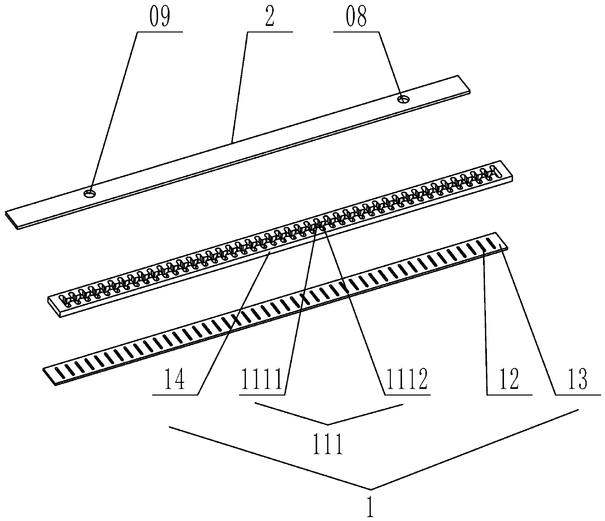
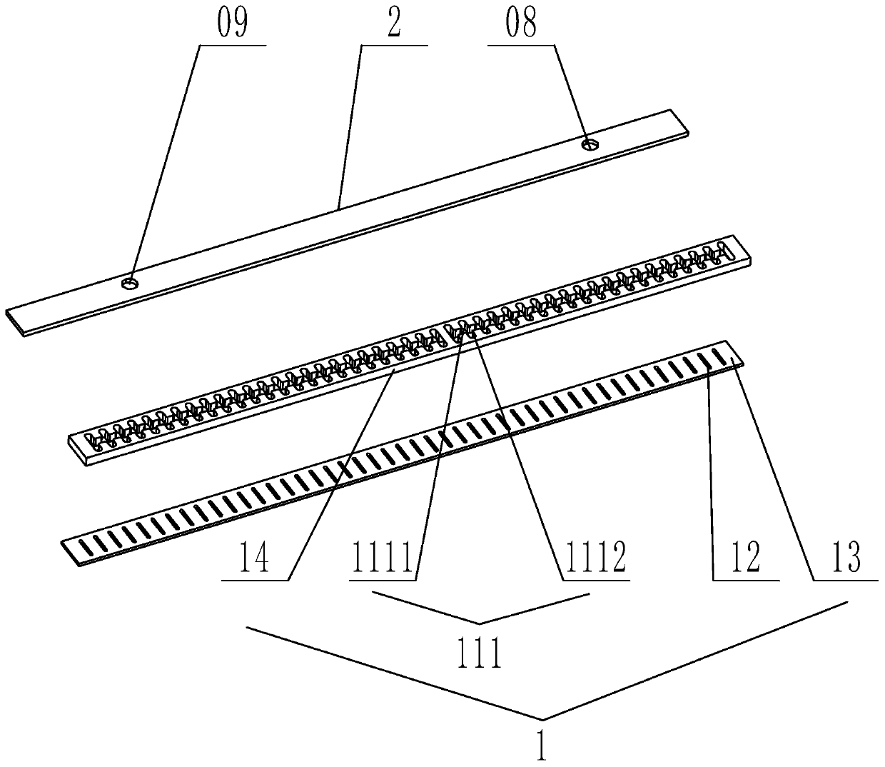
[0038] It should be noted that, for the convenience of description, there are "columns" and "rows" in this application. The direction of the column refers to the direction consistent with the extension direction of the current collecting plate 1, and the direction of the row refers to the direction perpendicular to the current collecting plate 1. The direction of the extension direction.

[0039] Such as figure 2 As shown, the present invention provides a collector assembly, including a collector assembly provided by the present invention, including a collector plate 1 and a cover plate 2, and the collector plate 1 includes a collector plate 1 body and a collector plate 1. The collecting chann...


PUM


Abstract

The invention relates to the technical field of heat exchange devices, in particular to a flow collecting pipe assembly and a heat exchanger. The flow collecting pipe assembly comprises a flow collecting plate and a cover plate. The flow collecting plate comprises a flow collecting plate body, a flow collecting channel and multiple insertion grooves, wherein the flow collecting channel and the multiple insertion grooves are formed in the flow collecting plate body. The multiple insertion grooves communicate with the flow collecting channel. In addition, in the thickness direction of the flow collecting plate, one end of the flow collecting channel is closed, and the other end of the flow collecting channel is opened. The cover plate is connected to the flow collecting plate in an overlapped manner so as to seal the other end of the flow collecting channel. The flow collecting pipe assembly is high in strength and convenient to machine.

Description

technical field [0001] The invention relates to the technical field of heat exchange devices, in particular to a header assembly and a heat exchanger. Background technique [0002] R134a is generally regarded as an environmentally friendly refrigerant in China. However, because GWP=1300 (Global Warming Potential) is too high, there is a lot of controversy in Europe, and it has been included in the phase-out procedure. Therefore, R134a is only used as a substitute in the transition to environmentally friendly products, and it is only a matter of time before it is fully phased out. As a natural working fluid, R744 has a GWP value of 1, and is one of the environmentally friendly substitutes for R134a. [0003] In addition to the above R134a refrigerant, CO can also be used 2 (R744) refrigerant; but relative to R134a refrigerant, CO 2 (R744) The working pressure of the refrigerant is significantly increased, and the header is also required to reach a burst pressure of 34MPa. ...

Claims


Application Information

Patent Timeline
IPC IPC(8): F28F9/02F25B39/00
CPCF28F9/02F25B39/00F28D1/05383F28D1/05391F28D2021/0068F28F9/0221F28F9/0278F28D1/05375
Inventor 丁天毅谢建褚树宝陈佳楠
Owner ZHEJIANG YINLUN MACHINERY
Why Eureka
Try Eureka