Heat exchanging tube and heat exchanger

A technology of heat exchange tubes and heat exchangers, applied in heat exchange equipment, tubular elements, lighting and heating equipment, etc., can solve the problems of inherent heat exchange performance reduction, heat release performance reduction, and large temperature difference, etc., to improve heat Exchange performance, reduced channel resistance, light weight effect

Inactive Publication Date: 2005-12-28
KEIHIN THERMAL TECH CORP
View PDF3 Cites 2 Cited by
  • Summary
  • Abstract
  • Description
  • Claims
  • Application Information

AI Technical Summary

Problems solved by technology

[0011] However, this method of weight reduction is considered to be limited, and further attempts to reduce weight according to this method would cause a reduction in the inherent heat exchange performance
For example, if the height of the heat exchange tube is lowered, the inner circumference of each refrigerant flow path is shortened, resulting in lower heat release performance; if the thickness of the outer peripheral wall of the heat exchange tube is set thinner, the pressure resistance capacity will be weakened
In addition, if the thickness of the fins is set thinner, the temperature difference between the portion where the fins are in contact with the heat exchange tubes and the portion where the fins are in the middle becomes larger, which also leads to a decrease in heat release performance.

Method used


Image

  • Heat exchanging tube and heat exchanger
  • Heat exchanging tube and heat exchanger
  • Heat exchanging tube and heat exchanger

Examples


example 1

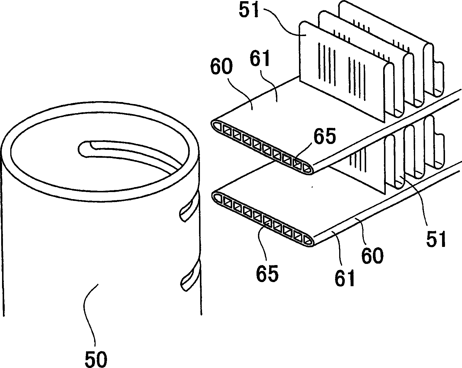
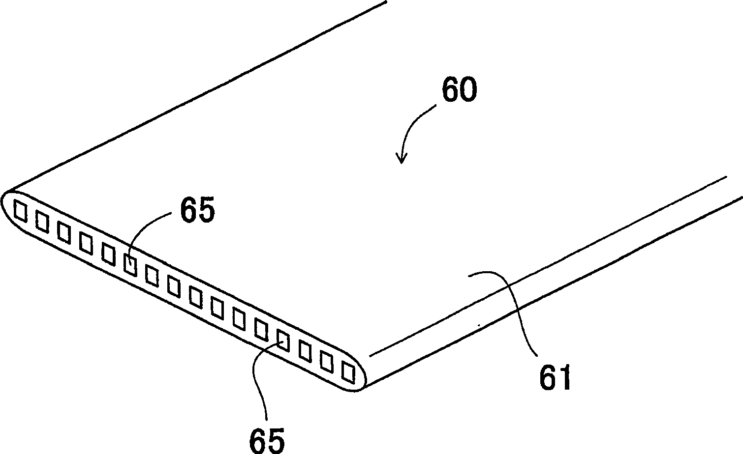
[0106] Manufacture according to the previously described embodiment (in image 3 with 4 Shown in) heat exchange tubes. As shown in Table 1, the total cross-sectional area Ac of the refrigerant channel is set to 5.29mm 2 , the total cross-sectional area At of the heat exchange tube body is set to 8.92mm 2 , the total inner perimeter P of the refrigerant channel is set to 64.1 mm, the outer perimeter L of the heat exchange tube body is set to 17.3 mm, the ratio of the total cross-sectional area of ​​the refrigerant channel to the cross-sectional area of ​​the heat exchange tube body Ac / At is set to 59%, the ratio P / L of the total inner circumference of the refrigerant channel to the outer circumference of the heat exchange tube body is set to 371%, the number N of refrigerant channels is set to 28, and the height of the heat exchange tube is H is set to 1.15mm, the width W of the heat exchange tube is set to 8mm, the ratio P / W of the total inner circumference of the refriger...

example 2

[0109] As shown in Table 1, the same as Example 1, manufacture such a heat exchange tube: Ac is set to 8.36mm 2 , At is set to 13.5mm 2 , P is set to 101.2mm, L is set to 25.3mm, Ac / At is set to 62%, P / L is set to 400%, N is set to 44, H is set to 1.15mm, W is set 12mm, P / W is set to 843%, N / W is set to 3.67 pieces / mm, Ta is set to 0.06mm, and Tb is set to 0.1mm. In addition, a heat exchanger using the heat exchange tube was manufactured.

example 3

[0111] As shown in Table 1, the same as Example 1, manufacture such a heat exchange tube: Ac is set to 11.3mm 2 , At is set to 18.1mm 2 , P is set to 131.8mm, L is set to 33.3mm, Ac / At is set to 63%, P / L is set to 396%, N is set to 57, H is set to 1.15mm, W is set 16mm, P / W is set to 824%, N / W is set to 3.56 pieces / mm, Ta is set to 0.06mm, and Tb is set to 0.1mm. In addition, a heat exchanger using the heat exchange tube was manufactured.


PUM


Abstract

The present invention relates to a heat exchange tube provided with a flat heat exchange tube main body having a predetermined length and a plurality of refrigerant passages extending longitudinally of the heat exchange tube and arranged transversely of the heat exchange tube. Satisfy the following relations (a) to (c): W=6 to 18mm...(a); Ac/At×100=50 to 70%...(b); P/L×100=350 to 450%...(c ), where "W" is the width of the heat exchange tube body, "Ac" is the total cross-sectional area of ​​the refrigerant channel, "At" is the total cross-sectional area of ​​the heat exchange tube body (including the refrigerant channel), "L " is the outer perimeter of the heat exchange tube body, and "P" is the total inner perimeter of the refrigerant passage. This heat exchange tube is light in weight, but can maintain sufficient pressure resistance and reduce channel resistance, thereby further improving its heat exchange performance.

Description

[0001] This application claims Japanese Patent Application No. 2002-290180, filed October 2, 2002, U.S. Provisional Patent Application No. 60 / 421,082, filed October 25, 2002, and Japanese Patent Application No. 60 / 421,082, filed September 19, 2003 Priority to Patent Application No. 2003-327179, the disclosure of which is hereby incorporated by reference in its entirety. [0002] Cross References to Related Applications [0003] This application is filed under 35 U.S.C § 111(a) and is claimed under 35 U.S.C § 119(e)(1) to the U.S. provisional application filed October 25, 2002 under 35 U.S.C § 111(b) Filing date entitlement of No. 60 / 421082. technical field [0004] The present invention relates to a heat exchanger, such as a condenser or an evaporator used in a refrigeration cycle of an automobile air conditioner, a household air conditioner, a refrigerator, an electronic equipment cooler, or similar products, and also relates to a method of the heat exchanger heat exchange ...

Claims


Application Information

Patent Timeline
Patent Type & Authority Applications(China)
IPC IPC(8): F28F1/02
Inventor 武幸一郎
Owner KEIHIN THERMAL TECH CORP
Why Eureka
Try Eureka