Indoor positioning and navigation method, device, and system
A technology for indoor positioning and positioning transmission, which is applied in the fields of navigation methods, indoor positioning, systems, and devices, and can solve problems such as low positioning accuracy and positioning result errors of RSSI indoor positioning technology
- Summary
- Abstract
- Description
- Claims
- Application Information
AI Technical Summary
Problems solved by technology
Method used
Image
Examples
Embodiment 1
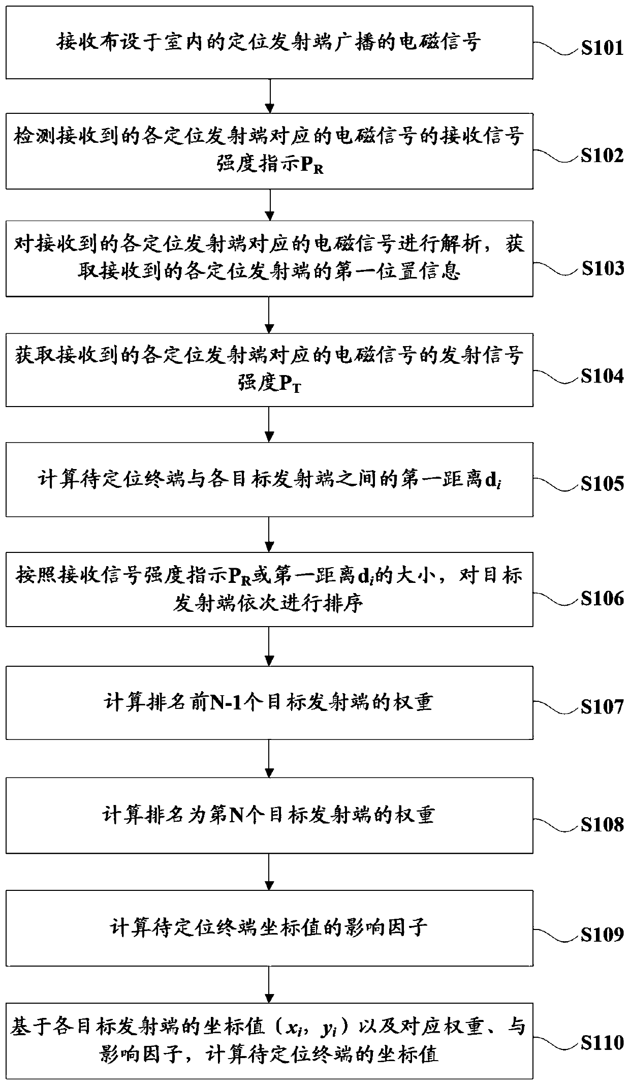
[0053] See figure 1 , figure 1 It is a schematic flow chart of the indoor positioning method of Embodiment 1, and the method mainly includes the following steps:
[0054] S101. Receive an electromagnetic signal broadcast by a positioning transmitter deployed indoors, where the electromagnetic signal carries first location information of the positioning transmitter itself.
[0055] This solution is mainly used in shopping malls, underground garages and other indoor areas to achieve precise positioning of vehicles and pedestrians. Vehicles can receive the electromagnetic signal broadcast by the positioning transmitter through the vehicle-mounted terminal, and pedestrians can receive the electromagnetic signal broadcast by the positioning transmitter through mobile terminals such as mobile phones.
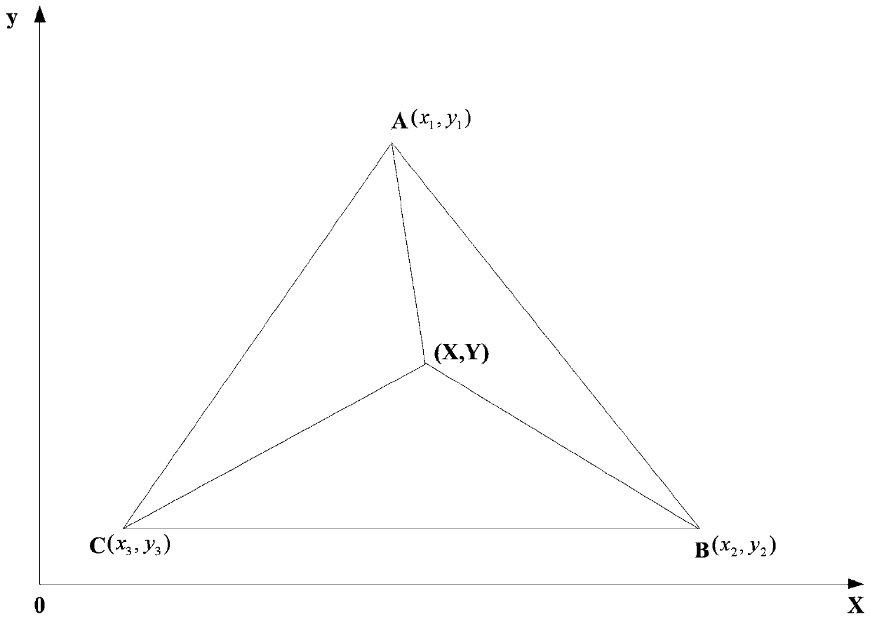
[0056] The positioning transmitter can be fixed at the set height position on the indoor wall, and try to be as horizontal as possible with the position of the terminal to be positi...
Embodiment 2
[0091] This embodiment provides an indoor navigation method on the basis of the first embodiment above, please refer to image 3 , the indoor navigation method mainly includes the following steps:
[0092] S301. Obtain an indoor electronic map.
[0093] The positioning transmitter or other equipment of the indoor positioning system can broadcast the indoor electronic map in real time, so that the terminal to be positioned can obtain it at the first time when it enters the area, and locate and navigate in time.
[0094] S302. Based on the coordinate values of the terminal to be positioned obtained by the indoor positioning method described in Embodiment 1 above, the location information of the terminal to be positioned is drawn and updated on the indoor electronic map to form a moving path of the terminal to be positioned.
[0095] After obtaining the current coordinate value of the terminal to be positioned, the coordinate value can be drawn in any existing way, so as to di...
Embodiment 3
[0097] On the basis of the first embodiment above, this embodiment provides an indoor positioning device, which is mainly used to implement the steps of the indoor positioning method described in the first embodiment above. Please refer to Figure 4 , the indoor positioning device 400 mainly includes the following modules:
[0098] The signal receiving module 401 is used to receive the electromagnetic signal broadcast by the positioning transmitter arranged indoors, and the electromagnetic signal carries the first location information of the positioning transmitter itself; the signal receiving module 401 includes but is not limited to a radio frequency antenna .
[0099] The signal detection module 402 is configured to detect the received signal strength indicator P of the electromagnetic signal corresponding to each positioning transmitter. R .
[0100] The signal processing module 403 is configured to analyze the received electromagnetic signal corresponding to each positi...
PUM
 Abstract
Description
Claims
Application Information
 - R&D
- Intellectual Property
- Life Sciences
- Materials
- Tech Scout
- Unparalleled Data Quality
- Higher Quality Content
- 60% Fewer Hallucinations
Browse by: Latest US Patents, China's latest patents, Technical Efficacy Thesaurus, Application Domain, Technology Topic, Popular Technical Reports.
© 2025 PatSnap. All rights reserved.Legal|Privacy policy|Modern Slavery Act Transparency Statement|Sitemap|About US| Contact US: help@patsnap.com


