
Autonomous dynamic wireless electric energy receiving device and method based on time inversion

A wireless power and receiving device technology, applied in circuit devices, battery circuit devices, current collectors, etc., can solve the problems of poor electromagnetic focusing effect, affecting the efficiency of wireless power transmission system, focusing beam deviation, etc., to solve the channel difference. , the effect of reducing the number of antennas and eliminating channel differences

Active Publication Date: 2019-08-13
UNIV OF ELECTRONICS SCI & TECH OF CHINA
View PDF11 Cites 6 Cited by
  • Summary
  • Abstract
  • Description
  • Claims
  • Application Information

AI Technical Summary

Problems solved by technology

Another example is the Chinese invention patent application with application number 201010568332.1, which discloses a wireless charging system and method for wireless sensor network nodes based on time reversal. The transmitting antenna and the receiving antenna are two antennas. Considering the mutual coupling between the antennas, a certain distance must be kept between the transmitting and receiving antennas, which leads to a certain difference in the transmission channels of the energy transmission request signal and the TR return signal. , which will cause the electromagnetic focusing effect at the receiving antenna to deteriorate and the focus spot or focused beam to deviate from the receiving antenna, which will directly affect the efficiency of the entire wireless power transmission system

Method used


Image

  • Autonomous dynamic wireless electric energy receiving device and method based on time inversion
  • Autonomous dynamic wireless electric energy receiving device and method based on time inversion
  • Autonomous dynamic wireless electric energy receiving device and method based on time inversion

Examples


Embodiment Construction

[0040] The present invention will be further described below in conjunction with the accompanying drawings and embodiments.

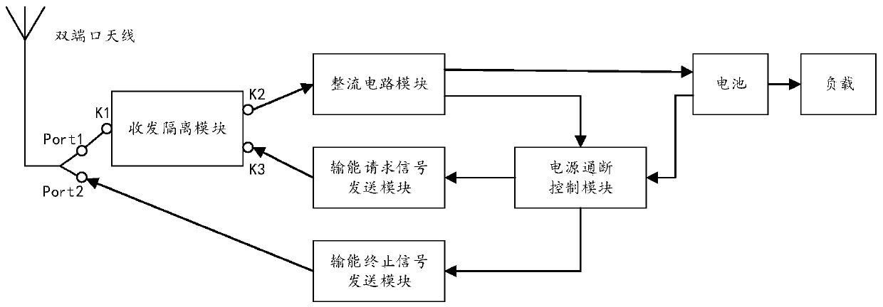
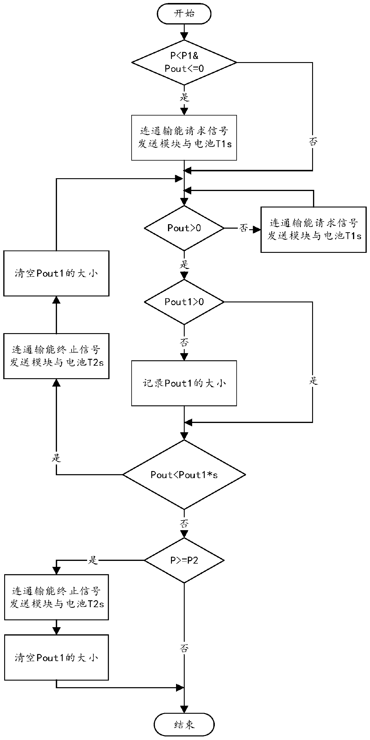
[0041] This embodiment provides an autonomous dynamic wireless power receiving device based on time inversion, and its structural diagram is as follows figure 1 As shown, it includes a dual-port antenna, a transceiver isolation module, a rectifier circuit module, an energy transmission request signal transmission module, an energy transmission termination signal transmission module, a power supply on-off control module and a battery;

[0042] The dual-port antenna includes 2 ports; the dual-port antenna can be a dual-frequency dual-port antenna, using different frequencies to achieve the independence of the two, or it can be a single-frequency dual-polarization dual-port antenna, using different polarization methods to achieve The independence of the two and other signal isolation technologies;

[0043] The transceiver isolation module includes 3 ports...


PUM


Abstract

The invention discloses an autonomous dynamic wireless power receiving device and method based on time inversion, and belongs to the technical field of wireless power transmission. According to the invention, the device achieves the uplink and downlink isolation of an energy transmission request signal and a time inversion return signal by using a transceiving isolation module, and achieves the transmission of the energy transmission request signal and the receiving of a time inversion return signal are transmitted through the same port of the same antenna, thereby eliminating the channel difference between the transmission process of the energy transmission request signal and the return process of the time inversion signal, and improving the wireless energy transmission efficiency. According to the invention, the device can control the starting stage, the stable transmission stage and the terminating stage of wireless electric energy transmission and the re-transmission of electric energy due to the movement of the receiving device and the change of transmission channel parameters, and achieves the purpose that a mobile receiving terminal autonomously completes the whole process of inversion of wireless electric energy receiving. According to the invention, the device can achieve the high-efficiency, movable and manual intervention-free autonomous time inversion wireless electric energy receiving.

Description

technical field [0001] The invention belongs to the technical field of wireless energy transmission, and in particular relates to an autonomous dynamic wireless energy receiving device and method based on time inversion. Background technique [0002] In recent years, with the rapid development of technologies such as smartphones, wearable electronics, smart homes, telemedicine, and unmanned factories, the number of various small and medium power wireless sensors and portable mobile devices has exploded. Powering these devices brings a series of problems such as high cost, regular battery replacement, and cumbersome cable layout. The use of wireless power supply makes these problems easily solved. The existing Wireless Power Transfer (WPT) technology is mainly performed through coil coupling or antenna directional radiation, which can only be applied to short-range or long-range point-to-point special scenarios, and the energy receiving end is too bulky. [0003] However, i...

Claims


Application Information

Patent Timeline
IPC IPC(8): H02J50/20H02J7/02
CPCH02J7/025H02J50/20
Inventor 胡林赵德双王秉中
Owner UNIV OF ELECTRONICS SCI & TECH OF CHINA
Learn More