Noise reduction vibration unit

A vibration unit, noise-reduction technology, applied in the field of noise-reduction vibration unit, can solve the problem of high mechanical noise

Inactive Publication Date: 2019-08-13
颂允科技(深圳)有限公司
View PDF4 Cites 0 Cited by
  • Summary
  • Abstract
  • Description
  • Claims
  • Application Information

AI Technical Summary

Problems solved by technology

[0004] The purpose of the present invention is to solve the disadvantage of high mechanical noise of the vibration unit in the prior art, and propose a noise-reducing vibration unit

Method used


Image

  • Noise reduction vibration unit
  • Noise reduction vibration unit

Examples


Embodiment Construction

[0016] The following will clearly and completely describe the technical solutions in the embodiments of the present invention with reference to the accompanying drawings in the embodiments of the present invention. Obviously, the described embodiments are only some, not all, embodiments of the present invention.

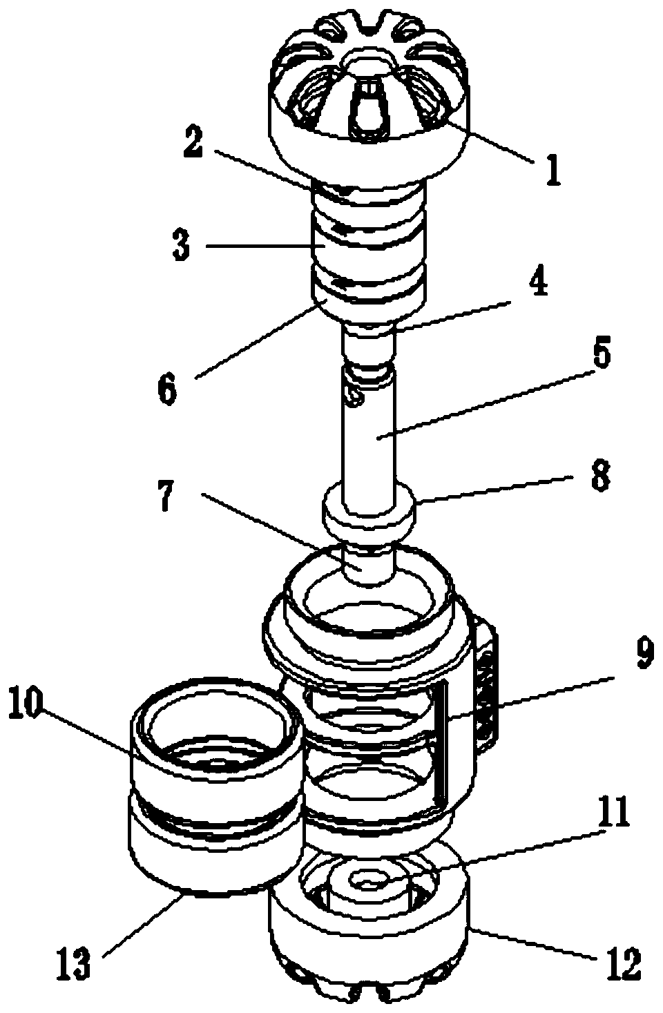
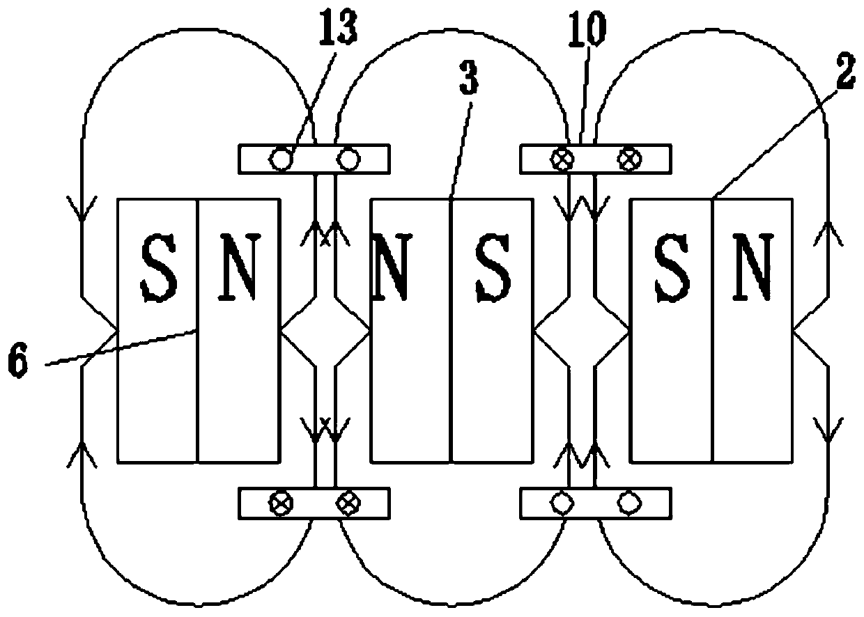
[0017] refer to Figure 1-2 , a noise reduction type vibration unit, comprising an upper suppression rubber cap 1, a housing 9 and a lower suppression rubber cap 12, the upper suppression rubber cap 1 and the lower suppression rubber cap 12 are provided with slots 11, and the upper suppression rubber cap 1 A fixed shaft 5 is connected with the lower restraining rubber cap 12, and the end of the fixed shaft 5 is inserted into the inner cavity of the slot 11 and connected with interference. The outer wall of the fixed shaft 5 is provided with a first strong magnet 2 and a second strong magnet. 3 and the third strong magnet 6, the outer wall of the fixed shaft 5 is inte...


PUM


Abstract

The invention relates to the technical field of vibration motors, in particular to a noise reduction vibration unit. The noise reduction vibration unit comprises an upper inhibition rubber cap, a shell and a lower inhibition rubber cap, and slots are formed in the upper inhibition rubber cap and the lower inhibition rubber cap. A fixed shaft is connected between the upper inhibition rubber cap andthe lower inhibition rubber cap, wherein the end part of the fixed shaft is inserted into the inner cavity of the slot and is in interference connection, and the outer wall of the fixed shaft is sleeved by a first strong magnet, a second strong magnet and a third strong magnet. A pair of limiting rings are integrally formed on the outer wall of the fixed shaft. The noise reduction vibration unitachieves a vibration function, and meanwhile, due to the elastic effect of the inhibition rubber caps, a magnet set is suspended at the center of a coil and is reset at the center of the coil, therebychanging the mode that vibration is achieved through inhibition of an elastic piece in existing electromagnetic driving. The whole magnet set cannot make contact with an elastic piece component, andmechanical noise cannot be generated in the working process, thereby achieving the effects of vibration and noise reduction.

Description

technical field [0001] The invention relates to the technical field of vibration motors, in particular to a noise reduction vibration unit. Background technique [0002] There are three types of vibrating devices in the market. One type uses a motor to drive the pendulum to rotate. The vibration frequency is directly related to the motor speed. The vibration frequency is difficult to control, and it is difficult to achieve an accurate vibration frequency effect. Noise, can not be synchronized with the audio, the other is to drive the vibration plate through the moving coil to achieve the effect of vibration, but the small power of the vibration sense cannot meet the product requirements, and cannot drive high-quality products. Another type is electromagnetic drive through shrapnel suppression. The effect of vibration is achieved, but the mechanical noise cannot be reduced. [0003] The prior art has the following disadvantages: no precise frequency and amplitude control, sm...

Claims


Application Information

Patent Timeline
Patent Type & Authority Applications(China)
IPC IPC(8): H02K33/16H02K5/24
CPCH02K5/24H02K33/16
Inventor 郑春平陈鹤杰
Owner 颂允科技(深圳)有限公司
Why Eureka
Try Eureka