Hardware machining copper and iron fragment separator

A technology for processing copper and separators, which is applied in the field of separators, can solve the problems of affecting work, iron fragments cannot be sucked, etc., and achieve the effect of convenient collection and processing

Active Publication Date: 2019-08-16
泰州市津专知识产权服务有限公司
View PDF9 Cites 2 Cited by
  • Summary
  • Abstract
  • Description
  • Claims
  • Application Information

AI Technical Summary

Problems solved by technology

[0002] After the hardware processing is completed, there will be a large number of copper fragments and iron fragments, which can be recycled, but the copper fragments and iron fragments are mixed together and need to be separated. The iron fragments are picked up and separated from the copper fragments, and the magnet needs to be moved continuously. After a long time, people are more tired and affect the follow-up work. After the iron fragments are sucked up, the iron fragments need to be removed by hand, which is troublesome. So people will directly pour the copper and iron fragments on the electromagnet for separation, and then collect them, so it is easy to cause some iron fragments to be unable to be attracted

Method used


Image

  • Hardware machining copper and iron fragment separator
  • Hardware machining copper and iron fragment separator
  • Hardware machining copper and iron fragment separator

Examples


Embodiment 1

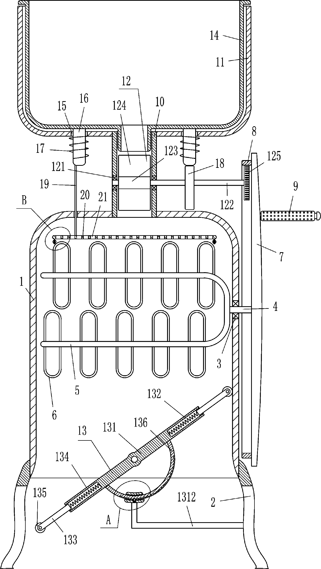
[0016] A metal processing copper and iron fragment separator, such as figure 1 As shown, it includes a box body 1, a leg 2, a first bearing seat 3, a first rotating shaft 4, a u-shaped rod 5, an electromagnet 6, a turntable 7, an inner gear ring 8, a rocker 9, a material tube 10, a frame Body 11 and rotating device 12, outriggers 2 are fixedly connected to the lower parts of the left and right sides of the box body 1, the box body 1 is connected to the outriggers 2 by means of bolt connection, the bottom of the box body 1 is open, and the first bearing seat 3 Embedded and installed on the upper right side of the box body 1, the first rotating shaft 4 is fixedly connected with the bearing in the first bearing seat 3, and the first rotating shaft 4 is connected with the bearing in the first bearing seat 3 through an interference connection. The left end of the first rotating shaft 4 is fixedly connected with a U-shaped rod 5, and a plurality of electromagnets 6 that can attract ...

Embodiment 2

[0018] A metal processing copper and iron fragment separator, such as figure 1 As shown, it includes a box body 1, a leg 2, a first bearing seat 3, a first rotating shaft 4, a u-shaped rod 5, an electromagnet 6, a turntable 7, an inner gear ring 8, a rocker 9, a material tube 10, a frame Body 11 and rotating device 12, outriggers 2 are fixedly connected to the lower parts of the left and right sides of the box body 1, the bottom of the box body 1 is open, the first bearing seat 3 is embedded in the upper right side of the box body 1, and the second A rotating shaft 4 is fixedly connected with the bearing in the first bearing seat 3, and the left end of the first rotating shaft 4 is fixedly connected with a u-shaped rod 5, and a plurality of electromagnets capable of attracting iron fragments are installed on the u-shaped rod 5 at even intervals 6. The turntable 7 is installed on the right end of the first rotating shaft 4. A rocker 9 is installed on the eccentric position on t...

Embodiment 3

[0021] A metal processing copper and iron fragment separator, such as Figure 1-2 As shown, it includes a box body 1, a leg 2, a first bearing seat 3, a first rotating shaft 4, a u-shaped rod 5, an electromagnet 6, a turntable 7, an inner gear ring 8, a rocker 9, a material tube 10, a frame Body 11 and rotating device 12, outriggers 2 are fixedly connected to the lower parts of the left and right sides of the box body 1, the bottom of the box body 1 is open, the first bearing seat 3 is embedded in the upper right side of the box body 1, and the second A rotating shaft 4 is fixedly connected with the bearing in the first bearing seat 3, and the left end of the first rotating shaft 4 is fixedly connected with a u-shaped rod 5, and a plurality of electromagnets capable of attracting iron fragments are installed on the u-shaped rod 5 at even intervals 6. The turntable 7 is installed on the right end of the first rotating shaft 4. A rocker 9 is installed on the eccentric position o...


PUM


Abstract

The invention relates to a separator and in particular to a hardware machining copper and iron fragment separator. The technical problem is to provide a hardware machining copper and iron fragment separator that can separate copper fragments from iron fragments instead of a worker, prevents the fatigue of the worker from affecting the subsequent work, and can conveniently collect iron fragments. The hardware machining copper and iron fragment separator comprises a box body, legs, a first bearing seat, a first rotating shaft, a u-shaped rod, an electromagnet and the like. The legs are fixedly connected to the lower parts of the left and the right sides of the box body; the box body has an open bottom; and the first bearing seat is embedded in the upper part of the right side of the box body. The copper and iron fragments are poured into a frame body and are dropped into a material tube to come into contact with a movable plate, and then by rocking a rocking rod, the movable plate can drop the copper and iron fragments into the box body to separate copper from iron by an electromagnet. The hardware machining copper and iron fragment separator avoids attracting the iron fragments witha magnet held by a hand, saves time and effort, and avoids fatigue of the workers from affecting the subsequent work.

Description

technical field [0001] The invention relates to a separator, in particular to a metal processing copper and iron fragment separator. Background technique [0002] After the hardware processing is completed, there will be a large number of copper fragments and iron fragments, which can be recycled, but the copper fragments and iron fragments are mixed together and need to be separated. The iron fragments are picked up and separated from the copper fragments, and the magnet needs to be moved continuously. After a long time, people are more tired and affect the follow-up work. After the iron fragments are sucked up, the iron fragments need to be removed by hand, which is troublesome. Therefore, people will directly pour the copper and iron fragments on the electromagnet for separation, and then collect them, so it is easy to cause some iron fragments to be unable to be attracted. Contents of the invention [0003] In order to overcome the need to constantly move the magnet, ...

Claims


Application Information

Patent Timeline
Patent Type & Authority Applications(China)
IPC IPC(8): B03C1/26
CPCB03C1/26
Inventor 唐金海
Owner 泰州市津专知识产权服务有限公司
Why Eureka
Try Eureka