Manufacturing method of metal forming body

A metal forming body and manufacturing method technology, applied in the direction of manufacturing tools, metal processing equipment, final product manufacturing, etc., can solve the problems of metal plate fracture, metal plate extension cannot follow the forming, etc., and achieve the effect of suppressing thin-walled

Inactive Publication Date: 2019-08-16
MITSUI HIGH TEC INC
View PDF5 Cites 0 Cited by
  • Summary
  • Abstract
  • Description
  • Claims
  • Application Information

AI Technical Summary

Problems solved by technology

However, when the flow path is dense and the shape is complex, the expansion of the metal plate cannot follow the forming, and the metal plate may break in some cases

Method used


Image

  • Manufacturing method of metal forming body
  • Manufacturing method of metal forming body
  • Manufacturing method of metal forming body

Examples


example 1

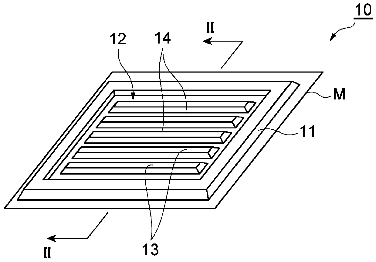
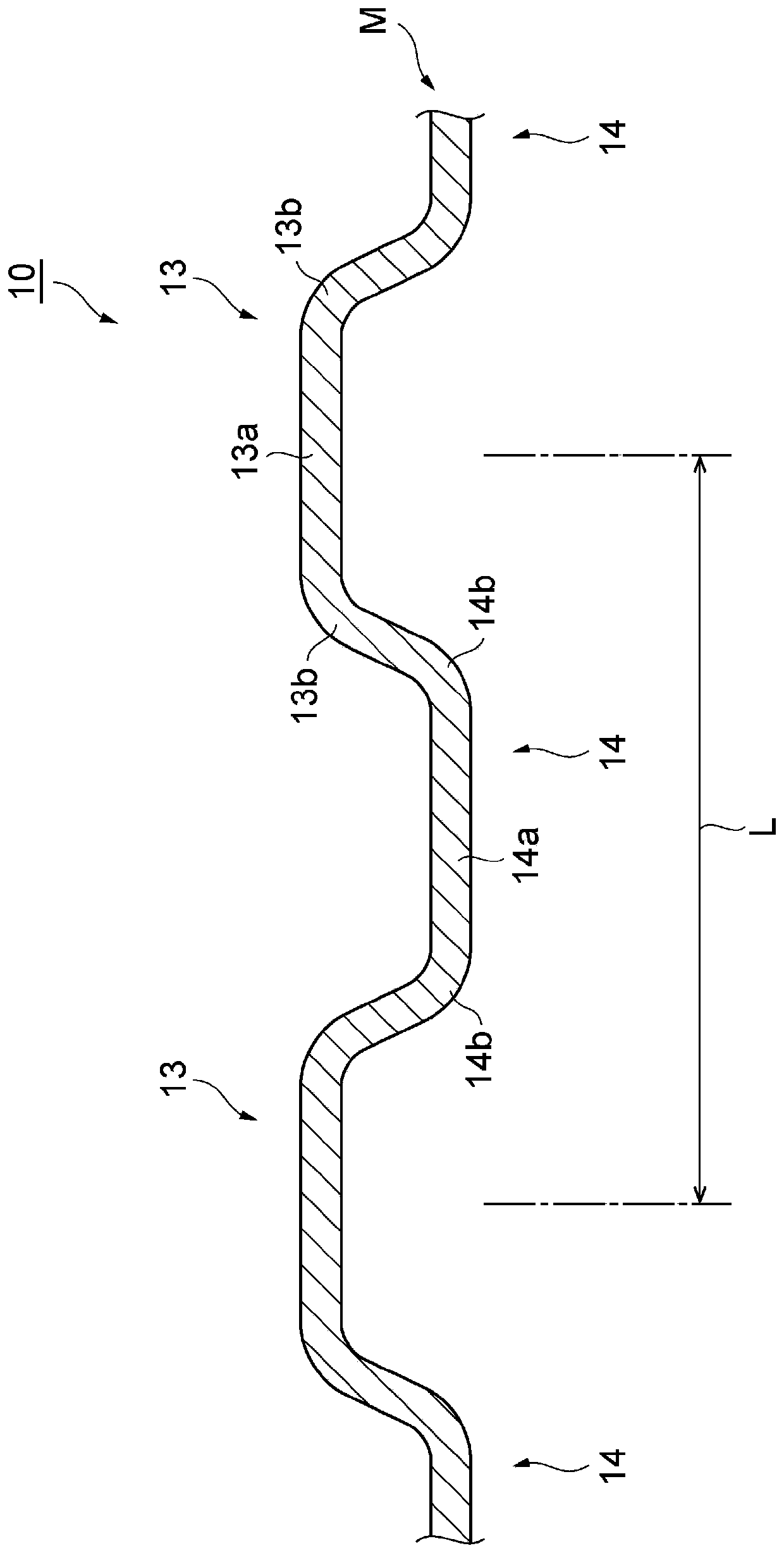
[0080] Example 1. A method of manufacturing a metal molded body 10 according to an example of the present invention. A flat metal sheet M is stretch-formed so that temporary concave portions 22 and temporary convex portions 21 are alternately arranged to form a temporary molded body 20. The metal formed body is characterized in that it includes: a step in which the temporary concave portion 22 and the temporary convex portion 21 respectively include the top walls 22a, 21a formed with the concave portions 22b, 21b depressed inwardly; The process of pushing the recessed parts 22b and 21b outward to form the molded body 10 in which the recessed parts 14 and the convex parts 13 are alternately arranged with the top walls 14a and 13a flat. In this case, since the temporary formed body 20 is formed by stretch forming, the metal plate M is not easily stretched even after being processed, unlike other processing methods such as spin forming, forging, and the like. Therefore, the thinn...

example 7

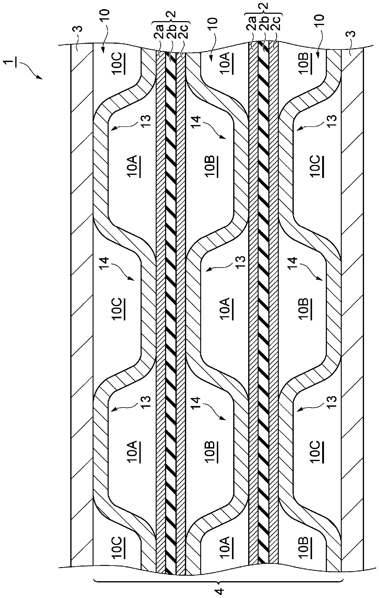
[0086] Example 7. A fuel cell stack 1 according to another example of the present disclosure is formed by alternately stacking metal separators 10 and membrane electrode assemblies 2 manufactured by the method of Example 6.


PUM


Abstract

The purpose of the present invention is to provide a method for manufacturing a metal molded body, which can suppress thinning of the corner portion, ensure a sufficient flat region, and flatten the ceiling wall. The method for manufacturing a metal molded body is characterized by comprising the following steps of: stretching and molding a flat metal plate so that temporary concave parts and temporary convex parts are alternately arranged to form a temporary molded body: a step in which the temporary concave portion and the temporary convex portion each include a top wall having a concave portion recessed inward; and a step of pressing the temporary formed body and pressing the recessed portions outward to form a formed body in which recessed portions and protruding portions are alternately arranged, the top wall of which is flat.

Description

technical field [0001] The invention relates to a method for producing a metal shaped body. Background technique [0002] Stamping is a method of manufacturing various shaped objects from sheet metal, and is one of the most efficient processing methods for mass-producing shaped objects. For example, as a separator used in a fuel cell for vehicle mounting, a separator processed from a graphite material has conventionally been used. A separator formed by stamping a metal plate. [0003] A thin-plate metal separator used in a fuel cell includes a plurality of flow paths through which fuel gas (for example, hydrogen gas) or air flows. When forming these flow paths, a pair of molds arranged with a metal plate interposed therebetween are used. Concave and convex flow paths are formed on a metal plate that has been punched and formed by a pair of dies. [0004] Production performance is more efficient if the sheet metal can be brought to its final shape in one stamping operatio...

Claims


Application Information

Patent Timeline
Patent Type & Authority Applications(China)
IPC IPC(8): B21D37/10B21D22/02B21D22/20
CPCB21D37/10B21D22/02B21D22/20Y02P70/50
Inventor 牧清久泉雅宏福永浩司松村拓哉
Owner MITSUI HIGH TEC INC
Why Eureka
Try Eureka