
Stretch and electromagnetic compound incremental forming method and device for large thin-walled parts

A large-scale thin-walled parts, electromagnetic composite technology, applied in the direction of forming tools, metal processing equipment, manufacturing tools, etc., can solve the problems of limiting sheet metal forming accuracy, low electromagnetic forming efficiency, poor forming accuracy, etc., to improve the utilization of discharge energy Ratio, improving sheet thickness distribution, increasing the effect of forming limit

Active Publication Date: 2016-09-07
HUAZHONG UNIV OF SCI & TECH
View PDF6 Cites 0 Cited by
  • Summary
  • Abstract
  • Description
  • Claims
  • Application Information

AI Technical Summary

Problems solved by technology

In the document "Investigation into a new hybrid forming process: Incremental sheet forming combined with stretch forming" (CIRP Annals–Manufacturing Technology), it is proposed to preform by deep drawing first, and then use a rigid tool head to roll and process detailed features. , which proves that the forming accuracy, sheet thickness distribution and forming time are all improved compared with the simple incremental forming method, but this incremental forming method has the following disadvantages: (1) The contact area between the rigid tool head and the sheet material is small, and the surrounding materials of the tool head are difficult to flow, so that the sheet material presents an overall thinning and deformation process, which limits the forming accuracy of the sheet material; (2) the rigid tool head is small in size and poor in rigidity, making it difficult to be suitable for accurate forming of high hardness and large thickness sheet metal; (3) rigidity The tool head is in direct contact with the sheet, there are obvious scratches on the surface of the sheet, and the forming quality of the sheet is poor
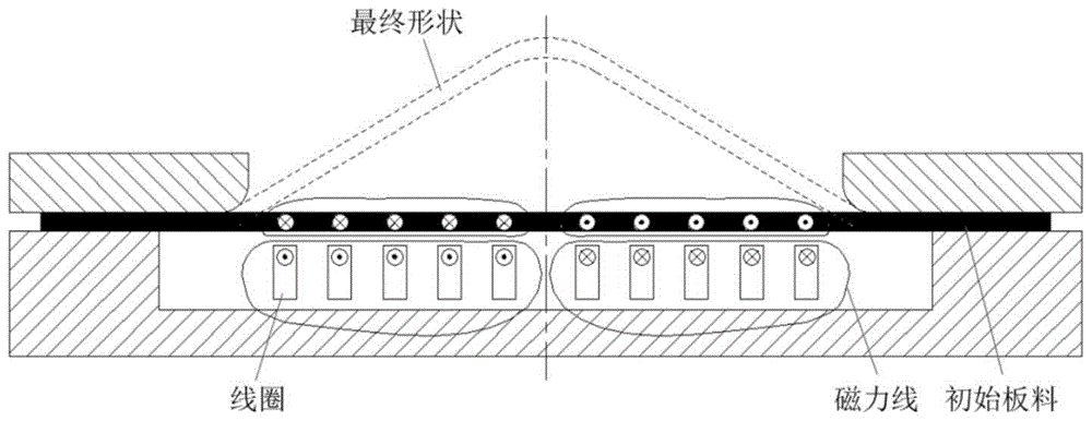
However, in the general flat electromagnetic pulse forming process, the discharge coil is in a fixed position, and its size should be consistent with the size of the mold. After one discharge, the metal sheet is bulged and finally formed into a conical part, such as figure 1 As shown, at the same time, it is difficult for this technology to directly realize the precise forming of large-size, deep-formed parts
Aiming at the electromagnetic processing of large-size plate-shaped parts, Mo Jianhua's research group at Huazhong University of Science and Technology carried out research on machining large-scale plates with moving electromagnetic pulse magnets based on a die. In the literature "Electromagnetic incremental forming (EMIF): a novel aluminum alloy sheet and In tubeforming technology", the electromagnet as a pulse discharge moves on the sheet material along the mold contour step by step, and discharges continuously at a position twice for each moving step. The first discharge makes the sheet material close to the mold contour, and the second discharge is In the previous step, the shape was calibrated and the sheet material was bonded to the mold. This research shows that the electromagnetic pulse incremental forming process can form large-size plate-shaped parts with small coils and small energy equipment. However, in this study, the sheet material is relatively fixed, There is no drawing process, and the coil has no swinging action, the height of the formed part is only 10mm, the forming accuracy is poor, and it is difficult to form large thin-walled parts; the publication number CN1821910A, the patent document published on August 23, 2006 discloses a The moving-coil electromagnetic progressive forming method and device for sheet metal proposes an electromagnetic forming method that uses small coils to form large-size sheet metal. It can move along the X, Y, and Z axes. It also has no drawing process, and the coil cannot swing relative to the clamping rod so that it can discharge directly to the area to be discharged. The electromagnetic forming efficiency is low, and the forming accuracy is difficult to control; In addition, electromagnetic forming is suitable for high-conductivity materials, but this patent is not suitable for deformation of low-conductivity materials such as high-strength steel, titanium alloys, composite materials, and plastics.

Method used


Image

  • Stretch and electromagnetic compound incremental forming method and device for large thin-walled parts
  • Stretch and electromagnetic compound incremental forming method and device for large thin-walled parts
  • Stretch and electromagnetic compound incremental forming method and device for large thin-walled parts

Examples


Embodiment Construction

[0037] In order to make the object, technical solution and advantages of the present invention clearer, the present invention will be further described in detail below in conjunction with the accompanying drawings and embodiments. It should be understood that the specific embodiments described here are only used to explain the present invention, not to limit the present invention. In addition, the technical features involved in the various embodiments of the present invention described below can be combined with each other as long as they do not constitute a conflict with each other.

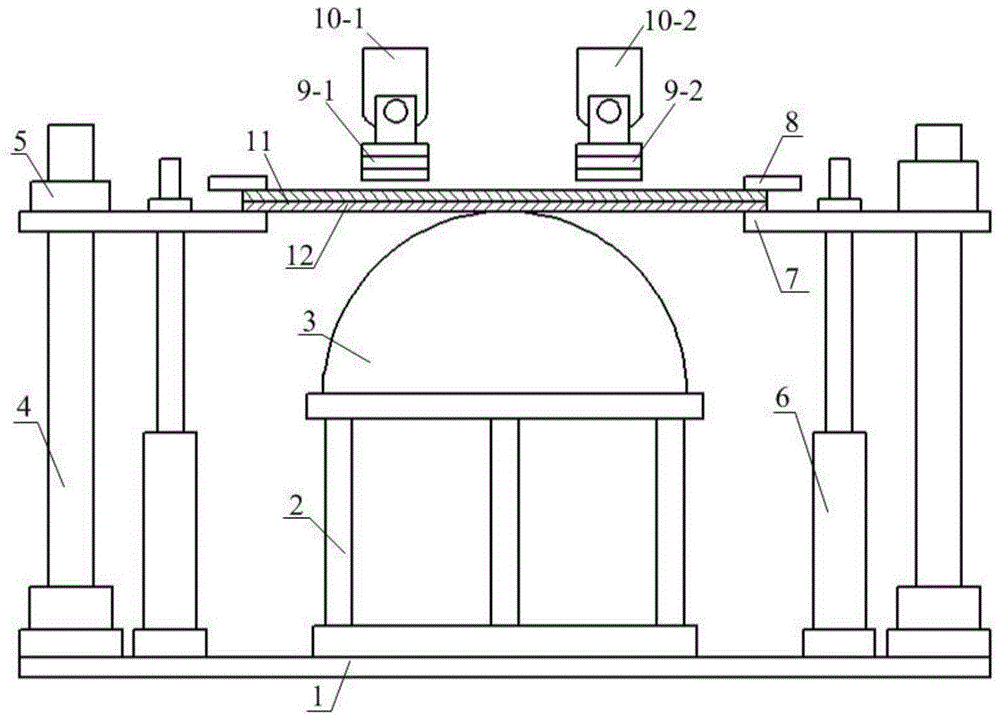
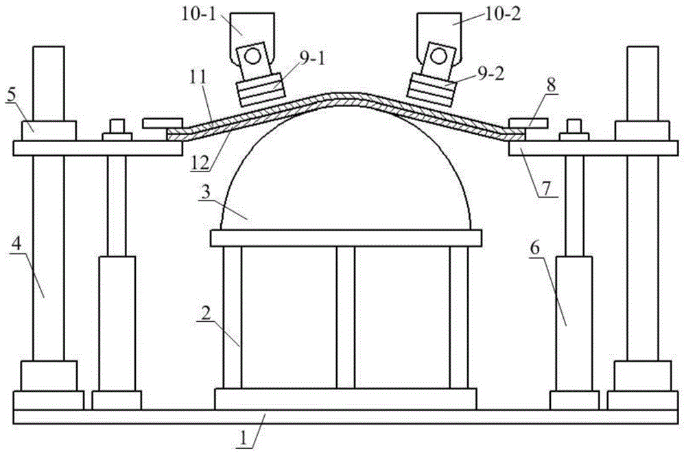
[0038] refer to Figure 2a-2e , a drawing and electromagnetic composite incremental forming device for large thin-walled parts based on a punch, including a base 1, a punch seat 2, a punch 3 arranged on the punch seat 2, a guide post 4, a guide sleeve 5, A lift cylinder 6, a drive plate 11, a plate to be deformed 12 for realizing the frame-shaped supporting plate 7 moving up and down along the ...


PUM


Abstract

The invention discloses a stretch-forming and electromagnetic combining incremental forming method and device of a large thin-wall part. The method comprises the steps that a driving plate is arranged above a plate to be deformed, the driving plate and the plate to be deformed are clamped by a pressing plate and a supporting plate, and a lifting oil cylinder drives the supporting plate to move, so that the driving plate and the plate to be deformed are stretch-bent and tightened preliminarily, and the stretch-forming process is achieved; the position of an electromagnetic coil is adjusted, the electromagnetic coil is made to exactly face the driving plate to be deformed to discharge electricity, the coil rotates on the surface of the driving plate for a circle around the axis of a male die, and the plate to be deformed is attached to the male die at the same height; then, the oil cylinder descends again to stretch-bend the plate, the coil discharges electricity to deform the plate to be deformed again, the plate to be deformed is attached to the male die, and the alternate forming process of stretch-forming, discharging, re-stretch-forming and re-discharging of the plate is achieved in the same way till deformation of the plate is finished. The flowing evenness of materials can be improved, the thinning ratio of the plate can be reduced, and flexible processing and precise plastic manufacturing of large plates hard to deform can be achieved.

Description

technical field [0001] The invention belongs to the field of progressive forming of plates, and more specifically relates to a drawing and electromagnetic composite progressive forming method and device for large thin-walled parts. Background technique [0002] With the rapid development of high-tech industries such as aerospace, it is urgent to adopt large-scale thin-walled shells with very significant structural benefits in advanced aircraft, spacecraft, rockets, and missiles to reduce weight, improve the load-carrying capacity limit and range of the carrier, etc. overall performance. Large-scale, thin-walled, light-weight, high-precision, high-strength, and good fatigue-resistant parts are typical representatives, such as large tank heads of spacecraft, cruise missile cabin sections, aircraft and spacecraft hoods , sub-tank and engine housing, etc. [0003] The plastic forming methods of large-scale shell components mainly include: (1) Using giant presses for powerful m...

Claims


Application Information

Patent Timeline
Patent Type & Authority Patents(China)
IPC IPC(8): B21D35/00B21D26/14B21D37/10
Inventor 李建军崔晓辉莫健华方进秀周波黄亮
Owner HUAZHONG UNIV OF SCI & TECH
Learn More