An auxiliary device applied to spring installation

An auxiliary device and spring installation technology, applied in the field of spring installation, can solve problems such as affecting work efficiency, easy scratching of hands, injury to staff, etc., and achieve the effects of improving work efficiency, improving the scope of application, and reducing unnecessary damage

Active Publication Date: 2021-02-09
深圳市诺亚创盟家具有限公司
View PDF5 Cites 0 Cited by
  • Summary
  • Abstract
  • Description
  • Claims
  • Application Information

AI Technical Summary

Problems solved by technology

[0004] However, in the process of actually installing springs, there are many springs that need to be installed on the bed board or sofa, and it is time-consuming and laborious for the staff to install the springs. If the workload is large, it will inevitably make the staff more tired, thereby affecting Work efficiency, and when pulling the spring, the hand is easy to scratch, which can easily cause unnecessary damage to the staff

Method used


Image

  • An auxiliary device applied to spring installation
  • An auxiliary device applied to spring installation
  • An auxiliary device applied to spring installation

Examples


Embodiment 1

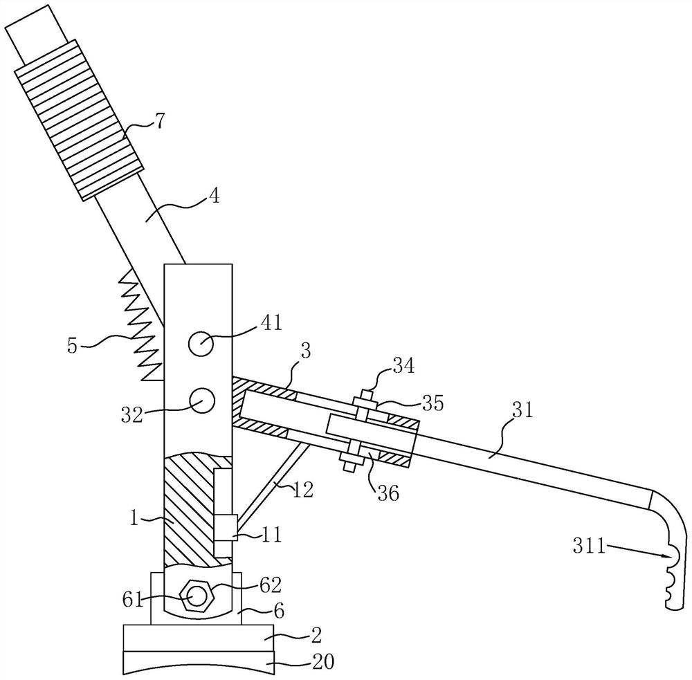
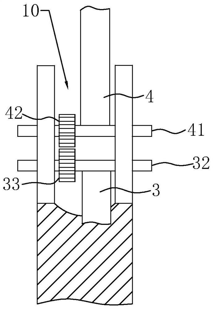
[0034] Embodiment 1: An auxiliary device applied to spring installation, such as figure 1 and figure 2 As shown, the fixed rod 1 is included, and a U-shaped through groove 10 is provided on the fixed rod 1, and a bottom plate 2 is fixed on the end of the fixed rod 1 away from the U-shaped through groove 10, and the bottom plate 2 can be connected with the frame of furniture such as sofa or bed board. match the edge of the board. In this embodiment, a hollow installation cylinder 3 is hinged in the U-shaped through groove 10, and a movable hook rod 31 is movably inserted in the installation cylinder 3, and the movable hook rod 31 can move along the extension direction of the installation cylinder 3. slide, and an adjustment assembly is provided on the installation cylinder 3, and the adjustment assembly can adjust the elongation of the movable hook rod 31.

[0035] Wherein, a rocker 4 is also hinged in the U-shaped through groove 10, and the end of the rocker 4 in the U-shap...

Embodiment 2

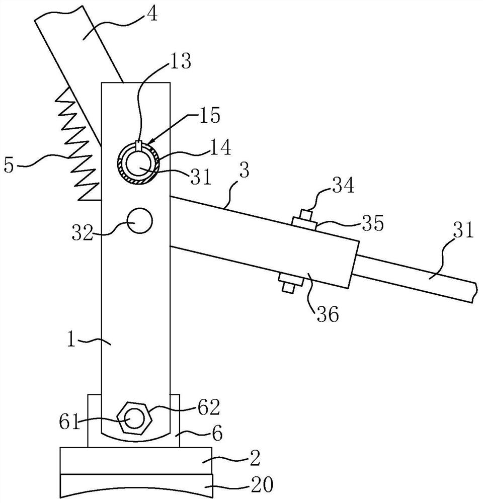
[0046] Embodiment 2: as image 3 As shown, the difference from Embodiment 1 lies in the difference of the limit assembly. In this embodiment, the limit assembly includes: the limit assembly includes: a limit block 13 fixed at the end of the first rotating rod 41, and An annular block 14 arranged around the outer wall of the fixed rod 1 around the first rotating rod 41; or a limit block 13 fixed at the end of the second rotating rod 32, and a fixed rod 1 ring arranged around the second rotating rod 32 The annular block 14 on the outer wall, the annular block 14 is apart from the first rotating rod 41 or the second rotating rod 32 preset distances, meanwhile, also offers a section arc groove 15 on the annular block 14, and the arc groove 15 can be with the position-limiting Block 13 matches, can limit the displacement that limit block 13 moves.

[0047] When the rocker 4 drives the mounting cylinder 3 to rotate, the first rotating rod 41 and the second rotating rod 32 will also...


PUM


Abstract

The invention relates to an auxiliary device for spring installation, which belongs to the technical field of spring installation. The key points of the technical solution include: a fixing rod with a U-shaped through groove; a bottom plate installed at the end of the fixing rod for pressing against the edge of the frame; The installation cylinder hinged in the U-shaped groove of the fixed rod; the movable hook rod inserted in the installation cylinder; the adjustment component on the installation cylinder for adjusting the extension length of the movable hook rod; hinged on the fixed rod away from the bottom plate The rocker on the side; the U-shaped through groove of the fixed rod is used to connect the installation cylinder and the rocker, so that the installation cylinder and the rocker are close to each other or away from the connection assembly; Install the limit assembly for the position of the cylinder and rocker. When the auxiliary device of the present invention is in use, the installation of the spring on the furniture can be realized conveniently, thereby reducing time and saving time, improving work efficiency, and effectively reducing injuries suffered by workers.

Description

technical field [0001] The invention relates to the technical field of spring installation, in particular to an auxiliary device applied to spring installation. Background technique [0002] In the furniture manufacturing process, such as the manufacture of some sofas and beds, in order to increase the softness and comfort of the furniture, springs are often installed inside the furniture to play a buffer role. [0003] At present, the process of installing springs in furniture is generally as follows: first, hooks need to be installed equidistantly on both sides of the frame of the bed or sofa, and then one end of the wave-shaped spring is fixed on the hook on one side of the frame, and then manually , to overcome the elasticity of the spring to pull the spring, so that the other end of the spring is hooked with the hook on the corresponding position on the other side of the frame plate, so as to realize the installation of the spring. [0004] However, in the process of a...

Claims


Application Information

Patent Timeline
Patent Type & Authority Patents(China)
IPC IPC(8): B25B27/30
CPCB25B27/30
Inventor 刘德武
Owner 深圳市诺亚创盟家具有限公司
Why Eureka
Try Eureka