
Prefabricated part stacking device

A technology of prefabricated components and braking mechanism, which is applied in the direction of tool storage devices, manufacturing tools, etc., can solve the problems of unable to store the quantity and types of prefabricated components, unfavorable fast and convenient access of prefabricated components, and failure of prefabricated components to enter the site on time, etc., to achieve Save on-site space, improve the level of intelligence, and the effect of simple assembly

Pending Publication Date: 2019-08-16
SHANGHAI CONSTR NO 5 GRP CO LTD
View PDF0 Cites 2 Cited by
  • Summary
  • Abstract
  • Description
  • Claims
  • Application Information

AI Technical Summary

Problems solved by technology

[0002] In the field of building construction, more and more prefabricated components are used to improve construction efficiency and reduce operation difficulty. However, due to the limited space on the construction site, it is impossible to store prefabricated components with a large number and types and large sizes.
At present, the scheduling problem of prefabricated components is usually solved by adjusting the entry time of prefabricated components. However, due to the influence of weather and transportation conditions, prefabricated components cannot enter the site on time and affect the construction progress; in addition, most of the existing prefabricated components are flat Placement, resulting in extremely low space utilization, if it is placed in multiple layers, it is not conducive to the rapid and convenient access of prefabricated components

Method used


Image

  • Prefabricated part stacking device
  • Prefabricated part stacking device
  • Prefabricated part stacking device

Examples


Embodiment Construction

[0024] In order to describe the technical solution of the above invention in more detail, specific examples are listed below to demonstrate the technical effect; it should be emphasized that these examples are used to illustrate the present invention and not limit the scope of the present invention.

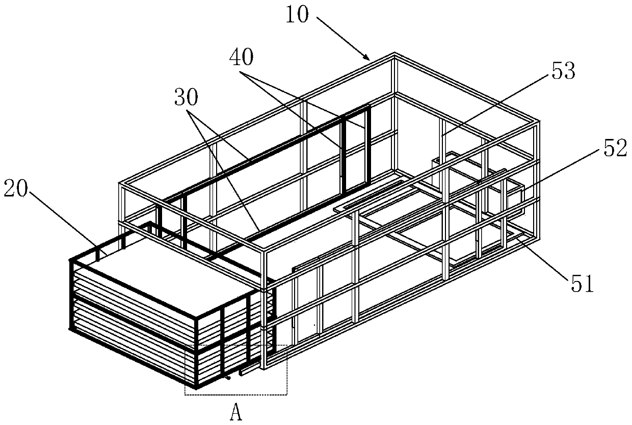
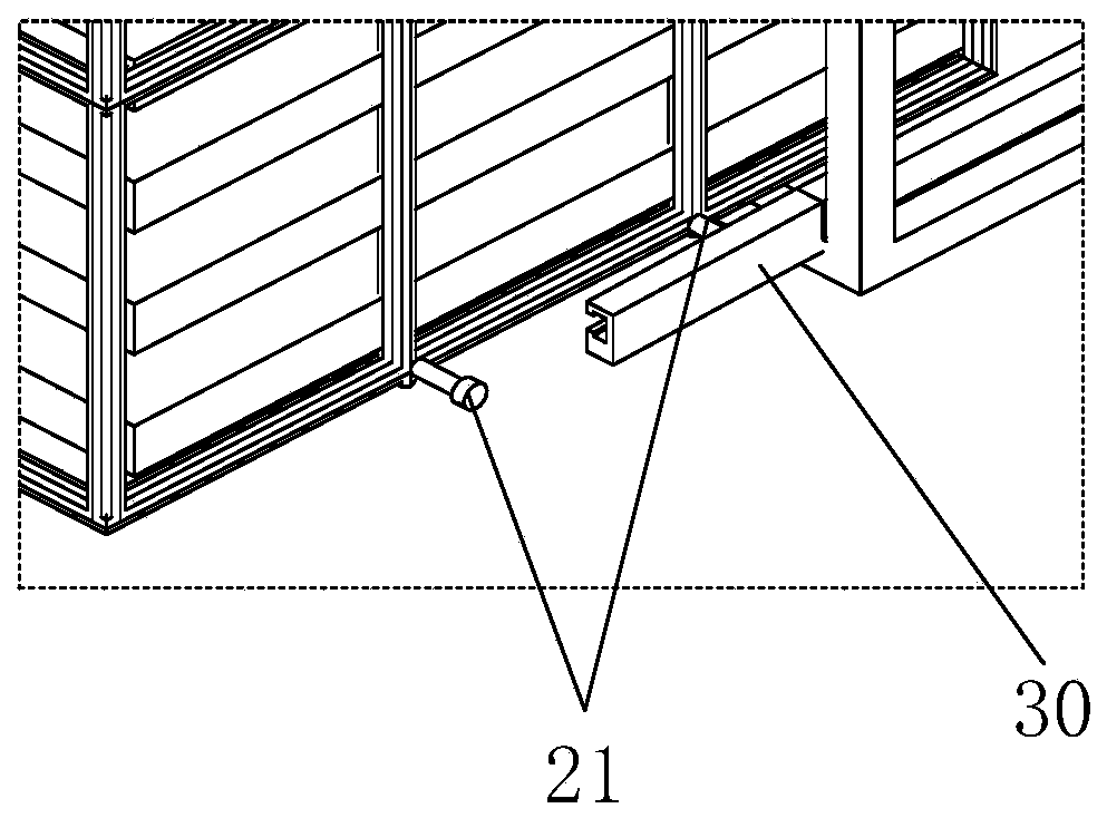
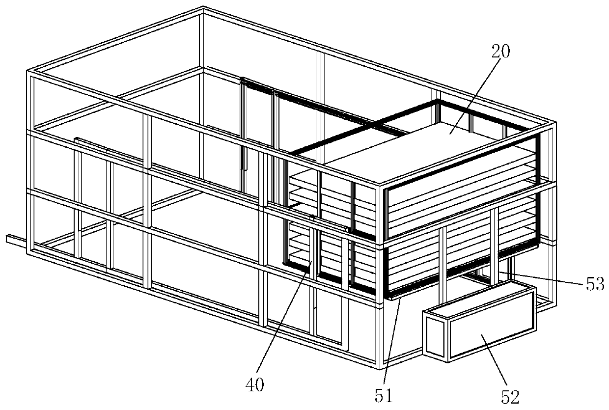
[0025] For the prefabricated component stacking device provided by the present invention, please refer to Figure 1 to Figure 4 , including: a steel frame 10 and several stacking baskets 20, the steel frame 10 is fixed with multi-layer horizontal chute 30, and multiple sets of vertical chute 40 are arranged between the two layers of horizontal chute 30, the vertical chute The end of the chute 40 communicates with the horizontal chute 30 ; the bottom of the stacking basket 20 is provided with a roller 21 , and the roller 21 can slide in the horizontal chute 30 and the vertical chute 40 . The present invention sets the horizontal chute 30 and the vertical chute 40, utilizes the sli...


PUM


Abstract

The invention relates to a prefabricated part stacking device. The device comprises a steel framework and a plurality of stacking baskets, a plurality of layers of transverse sliding grooves are fixedon the steel framework, a plurality of groups of vertical sliding grooves are formed between two layers of transverse sliding grooves, the ends of the vertical sliding grooves communicate with the transverse sliding grooves, rotating wheels are arranged at the bottom of the stacking baskets, and the rotating wheels can slide in the transverse sliding grooves and the vertical sliding grooves. According to the device, the transverse sliding grooves and the vertical sliding grooves are formed, movement on horizontal position of the stacking baskets can be realized by utilizing sliding of the rolling wheels in the transverse sliding grooves, movement at vertical direction of the stacking baskets is realized by utilizing sliding of the rolling wheels in the vertical sliding grooves, so that multi-dimensional storage of prefabricated parts is realized, the stacking quantity of the prefabricated parts is greatly increased, the field space is saved, the stacking baskets are convenient to move, and the prefabricated parts are convenient to take.

Description

technical field [0001] The invention relates to the field of building construction, in particular to a prefabricated component stacking device. Background technique [0002] In the field of building construction, more and more prefabricated components are used to improve construction efficiency and reduce operation difficulty. However, due to the limited space on the construction site, it is impossible to store prefabricated components with a large number and types and large sizes. At present, the scheduling problem of prefabricated components is usually solved by adjusting the entry time of prefabricated components. However, due to the influence of weather and transportation conditions, prefabricated components cannot enter the site on time and affect the construction progress; in addition, most of the existing prefabricated components are flat If it is placed in multiple layers, it is not conducive to the quick and convenient access of prefabricated components. [0003] T...

Claims


Application Information

Patent Timeline
Patent Type & Authority Applications(China)
IPC IPC(8): B25H3/04
CPCB25H3/04
Inventor 时春霞潘峰韩亚明曹刘坤沈浅灏徐沈京
Owner SHANGHAI CONSTR NO 5 GRP CO LTD
Learn More