
Bottle billet forming part assembly with die cavity extending into die lip for matching and bottle billet die thereof

A technology of mold cavity and mold lip, which is applied in the field of preform molding parts assembly and preform mold, which can solve the problems of reduced strength of die lip cone surface, poor cooling effect, affecting service life, etc., and achieves improved connection stability , The cooling effect is fully uniform, and the cooling effect is uniform and sufficient

Pending Publication Date: 2019-08-16
GUANG DONG XING LIAN PRECISE MACHINERY
View PDF0 Cites 0 Cited by
  • Summary
  • Abstract
  • Description
  • Claims
  • Application Information

AI Technical Summary

Problems solved by technology

[0005] 1. If figure 1 As shown, in the assembly structure design of the preform molding parts, the connection between the cavity and the lip is planar. In order to make the anti-theft ring and the support ring at the billet mouth have a good cooling effect during the molding process, The anti-theft ring and the support ring forming part will be set near the cooling water channel of the die lip, but this structural design will cause the parting line between the cavity and the die lip to be formed in the shoulder area of ​​the preform, causing the preform to be stretched and blown. After the bottle is formed, the parting line will produce obvious horizontal lines on the shoulder of the bottle with the stretching of the preform, which will affect the appearance of the bottle
[0006] 2. If figure 2 As shown, in the existing design, in order to solve the problems existing in Form 1, the design of the mold core clamping ring extending into the die lip structure is adopted. One end of the parting line between the cavities is moved so that the parting line is in the neck forming area of ​​the body. Since the neck forming area of ​​the body hardly participates in stretching during the preform stretch blow molding, the bottle is formed No obvious horizontal line will be produced after the end, but the anti-theft ring of the bottle mouth and the forming part of the support ring of this design structure are far away from the cooling water channel of the die lip, and the cooling effect is not good, which is easy to cause shrinkage and deformation here. The distance between the cone surface of the die lip is relatively close, resulting in a decrease in the strength of the cone surface of the die lip and affecting its service life
[0007] 3. If image 3 A bottle preform mold shown includes a cavity and a die lip, the cavity and the die lip are connected by a cavity fastener, and the parting surface between the cavity and the die lip is set on the body neck and the support The junction of the rings further eliminates the influence of the parting line of the bottle body on the appearance of the bottle, but the anti-theft ring of the bottle mouth and the forming part of the support ring of this design structure are far away from the cooling water channel of the die lip, and the cooling effect is not good, which is easy to cause here Shrinkage deformation, so it is necessary to improve the preform mold for the above technical problems

Method used


Image

  • Bottle billet forming part assembly with die cavity extending into die lip for matching and bottle billet die thereof
  • Bottle billet forming part assembly with die cavity extending into die lip for matching and bottle billet die thereof
  • Bottle billet forming part assembly with die cavity extending into die lip for matching and bottle billet die thereof

Examples


Embodiment 1

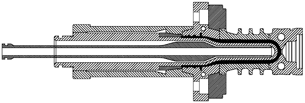
[0040] This embodiment discloses a bottle preform forming part assembly in which the mold cavity goes deep into the lip and fits, including a mold cavity 1, a mold lip 2, a mold core 3 and a mold cavity fastener 4, and the mold cavity fastener 4 is located at Between the mold cavity 1 and the die lip 2, the die lip 2 and the mold cavity fastener 4 adopt a taper fit, and the mold cavity fastener 4 is sleeved on the outer surface of the mold cavity 1 and the die lip 2 At the junction, the die lip 2 is provided with a die lip cooling channel 21, the end of the die cavity 1 is provided with a flange 11, and the end of the die lip 2 is provided with a fitting hole 22, and the fitting hole The position 22 is sleeved on the outer wall of the flange 11, and the mating end surface between the flange 11 and the matching hole 22 forms a billet parting surface 5, and the billet body parting surface 5 is arranged on the neck A1 of the billet body for forming In this embodiment, the flange ...

Embodiment 2

[0044] This embodiment discloses a preform mold in which the cavity is deeply matched with the lip, which includes a preform forming part assembly and a cavity bottom 6, the cavity bottom 6 is installed at the end of the cavity 1 away from the lip 2, so The bottom of the mold cavity 6 is provided with a bottom cavity 61 for forming the bottom of the preform, and the bottom of the cavity 6 is provided with a cooling channel 62 at the bottom of the cavity, and the cooling channel 62 at the bottom of the cavity surrounds the cavity at the bottom of the blank 61 peripheral settings. It also includes a core cooling pipe 7, which extends along the central axis of the core 3 to the inside of the core 3, and the core cooling pipe 7 is a U-shaped structure. The core cooling pipe 7 is provided with a hollow convex body 71 for improving the cooling effect of the mold core 3. The hollow convex body 71 is arranged at a position corresponding to the billet cavity 23. The core cooling pipe 7...


PUM


Abstract

The invention discloses a bottle billet forming part assembly with a die cavity extending into a die lip for matching. The bottle billet forming part assembly comprises a die cavity, a die lip, a diecore and a die cavity fastener, wherein the die cavity fastener is positioned between the die cavity and the die lip; a die lip cooling water channel is arranged in the die lip; a flange is arranged at the end part of the die cavity; a matching hole site is formed in the end part of the die lip and is connected with the outer side wall of the flange in a sleeving manner; a matching end face between the flange and the matching hole site forms a billet body parting surface; and the billet body parting surface is arranged on a billet body neck forming area. The invention further discloses a bottle billet die with the die cavity extending into the die lip for matching. The bottle billet die comprises the bottle billet forming part assembly and a die cavity bottom; the die cavity bottom is mounted at the end, far away from the die lip, of the die cavity; a billet bottom cavity for forming the bottle billet bottom is formed in the die cavity bottom; a die cavity bottom cooling water channelis formed in the die cavity bottom; and the die cavity bottom cooling water channel surrounds the periphery of the billet bottom cavity.

Description

technical field [0001] The invention relates to the field of preform moulds, in particular to a preform molding part assembly with a mold cavity deep into a die lip and a preform mold thereof. Background technique [0002] At present, in the structural design of PET (polyethylene terephthalate) preform molds for rapid multi-cavity, most of the mold parting surface, the cooling design of the bottle mouth part, and the strength of the die lip are all affected by the product classification. Due to the limitation of the mold requirements, the cooling effect of the mouth of some molds and the strength of the die lip cannot reach the ideal value, and the injection cycle of the mold produced and the service life of the mold are affected to a certain extent. [0003] The die lip plays an important role in the PET bottle preform mold, and the inner diameter of the preform, the thread of the preform, and the support ring of the preform are all concentrated in it. The inner diameter o...

Claims


Application Information

Patent Timeline
IPC IPC(8): B29C45/26B29C45/73
CPCB29C45/2602B29C45/261B29C45/7312
Inventor 谢国基姜晓平董书生卢佳黎同毅
Owner GUANG DONG XING LIAN PRECISE MACHINERY
Learn More