Mold rapid cooling device and using method thereof
A rapid cooling and mold technology, applied in the field of mold cooling, can solve the problems of poor cooling effect and slow cooling speed
- Summary
- Abstract
- Description
- Claims
- Application Information
AI Technical Summary
Problems solved by technology
Method used
Image
Examples
Embodiment 1
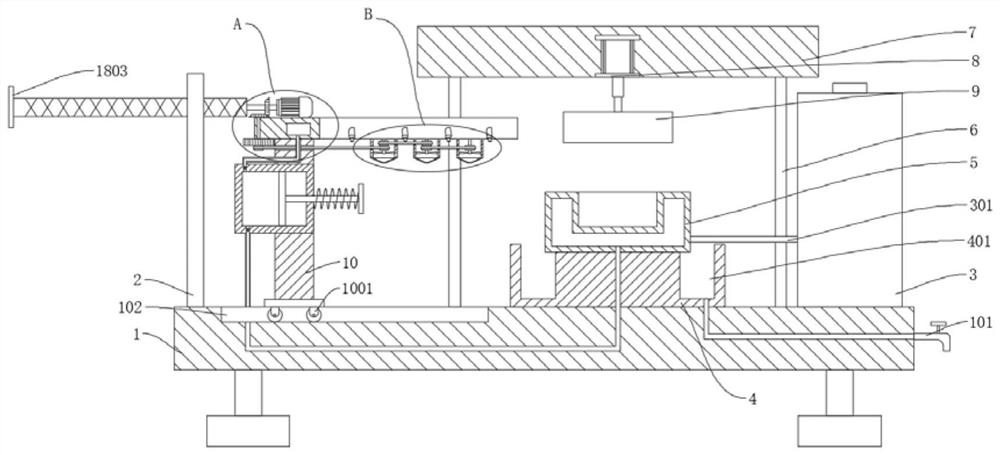
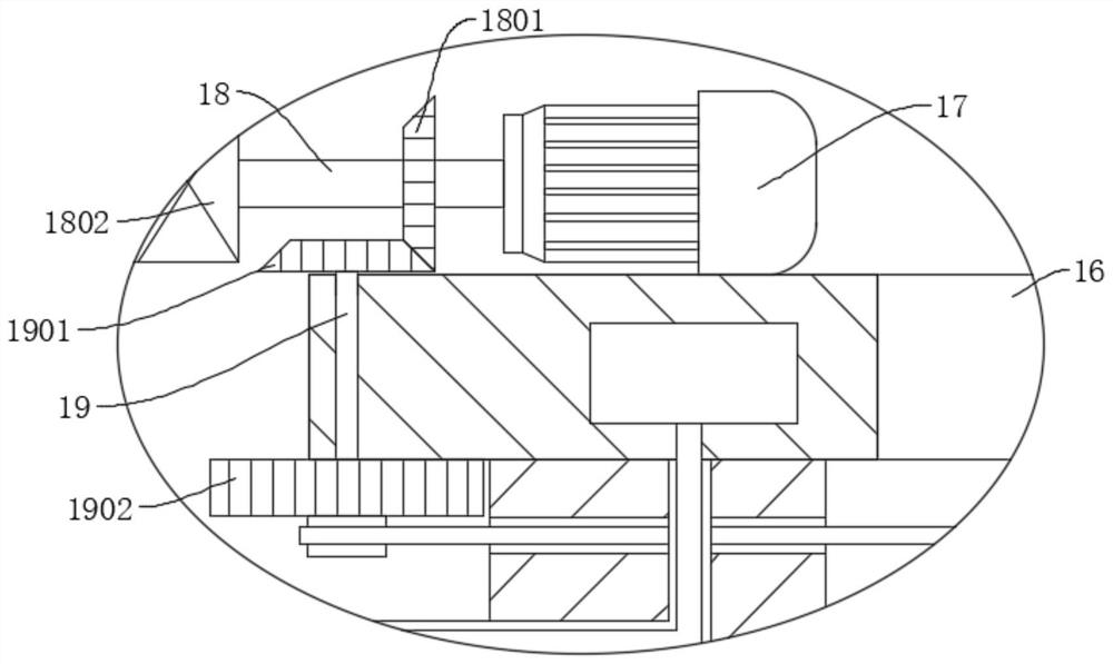
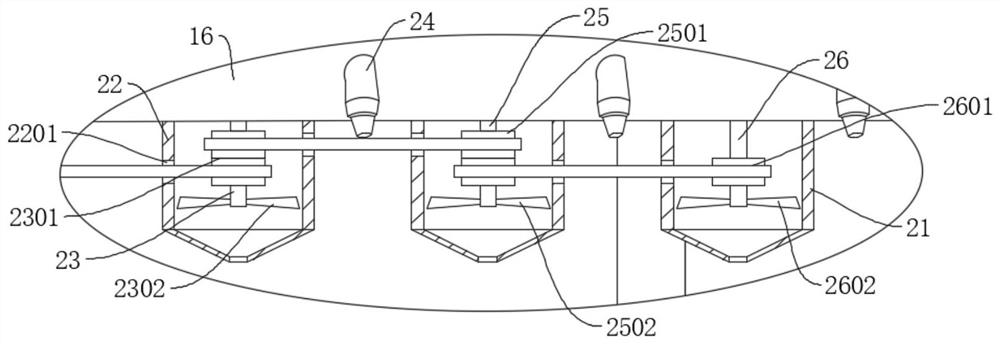
[0037]Referencefigure 1 ,figure 2 ,Figure 4 ,Figure 5 withFigure 7, A rapid mold cooling device, comprising a base 1, the outer wall of the base 1 is fixedly connected with a mold base 4, the top outer wall of the mold base 4 is fixedly connected with a lower mold 5, the outer wall of the base 1 is fixedly connected with a support rod 6, and the support rod 6 is away from the base 1. One end is fixedly connected to the top seat 7, the top seat 7 is provided with a cylinder 8, the output end of the cylinder 8 is fixedly connected to the upper mold 9, the base 1 is slidably connected with a stabilizer plate 10, and the stabilizer plate 10 is fixedly connected with a piston cylinder 11. The piston cylinder 11 is provided with a second water inlet pipe 1101 and a water outlet pipe 1102. The second water inlet pipe 1101 and the water outlet pipe 1102 are both provided with a one-way valve 1103. The piston cylinder 11 is slidably connected with a piston plate 12, and the outer wall of the...
Embodiment 2
[0048]Reference mapimage 3 withFigure 6 , A rapid mold cooling device, comprising a base 1, the outer wall of the base 1 is fixedly connected with a mold base 4, the top outer wall of the mold base 4 is fixedly connected with a lower mold 5, the outer wall of the base 1 is fixedly connected with a support rod 6, and the support rod 6 is away from the base 1. One end is fixedly connected to the top seat 7, the top seat 7 is provided with a cylinder 8, the output end of the cylinder 8 is fixedly connected to the upper mold 9, the base 1 is slidably connected with a stabilizer plate 10, and the stabilizer plate 10 is fixedly connected with a piston cylinder 11. The piston cylinder 11 is provided with a second water inlet pipe 1101 and a water outlet pipe 1102. The second water inlet pipe 1101 and the water outlet pipe 1102 are both provided with a one-way valve 1103. The piston cylinder 11 is slidably connected with a piston plate 12, and the outer wall of the piston plate 12 is fixed....
Embodiment 3
[0059]Referencefigure 1 withFigure 4 , A rapid mold cooling device, comprising a base 1, the outer wall of the base 1 is fixedly connected with a mold base 4, the top outer wall of the mold base 4 is fixedly connected with a lower mold 5, the outer wall of the base 1 is fixedly connected with a support rod 6, and the support rod 6 is away from the base 1. One end is fixedly connected to the top seat 7, the top seat 7 is provided with a cylinder 8, the output end of the cylinder 8 is fixedly connected to the upper mold 9, the base 1 is slidably connected with a stabilizer plate 10, and the stabilizer plate 10 is fixedly connected with a piston cylinder 11. The piston cylinder 11 is provided with a second water inlet pipe 1101 and a water outlet pipe 1102. The second water inlet pipe 1101 and the water outlet pipe 1102 are both provided with a one-way valve 1103. The piston cylinder 11 is slidably connected with a piston plate 12, and the outer wall of the piston plate 12 is fixed. A ...
PUM
 Abstract
Description
Claims
Application Information
 - R&D
- Intellectual Property
- Life Sciences
- Materials
- Tech Scout
- Unparalleled Data Quality
- Higher Quality Content
- 60% Fewer Hallucinations
Browse by: Latest US Patents, China's latest patents, Technical Efficacy Thesaurus, Application Domain, Technology Topic, Popular Technical Reports.
© 2025 PatSnap. All rights reserved.Legal|Privacy policy|Modern Slavery Act Transparency Statement|Sitemap|About US| Contact US: help@patsnap.com


