
Adjustable constant-force screen manufacturing device and application method thereof

A production device and adjustable technology, which can be applied to other home appliances, nets, applications, etc., can solve problems affecting performance, looseness of the screen, insufficient tension, etc., and achieve convenient operation, improved production efficiency, and simple structure Effect

Pending Publication Date: 2019-08-16
PUYANG ZHONGYUAN RUISHIDA PETROLEUM EQUIP CO LTD
View PDF0 Cites 0 Cited by
  • Summary
  • Abstract
  • Description
  • Claims
  • Application Information

AI Technical Summary

Problems solved by technology

However, during production, due to the insufficient tension of the screen, the phenomenon of screen loosening will directly affect the performance, especially after a period of use, the loosening of the screen will be more serious, so it has to be frequently used during use. Replacement is both troublesome and increases the cost of use

Method used


Image

  • Adjustable constant-force screen manufacturing device and application method thereof
  • Adjustable constant-force screen manufacturing device and application method thereof
  • Adjustable constant-force screen manufacturing device and application method thereof

Examples


Embodiment Construction

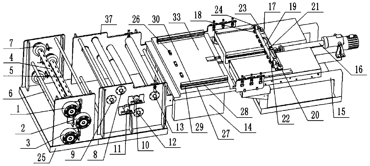
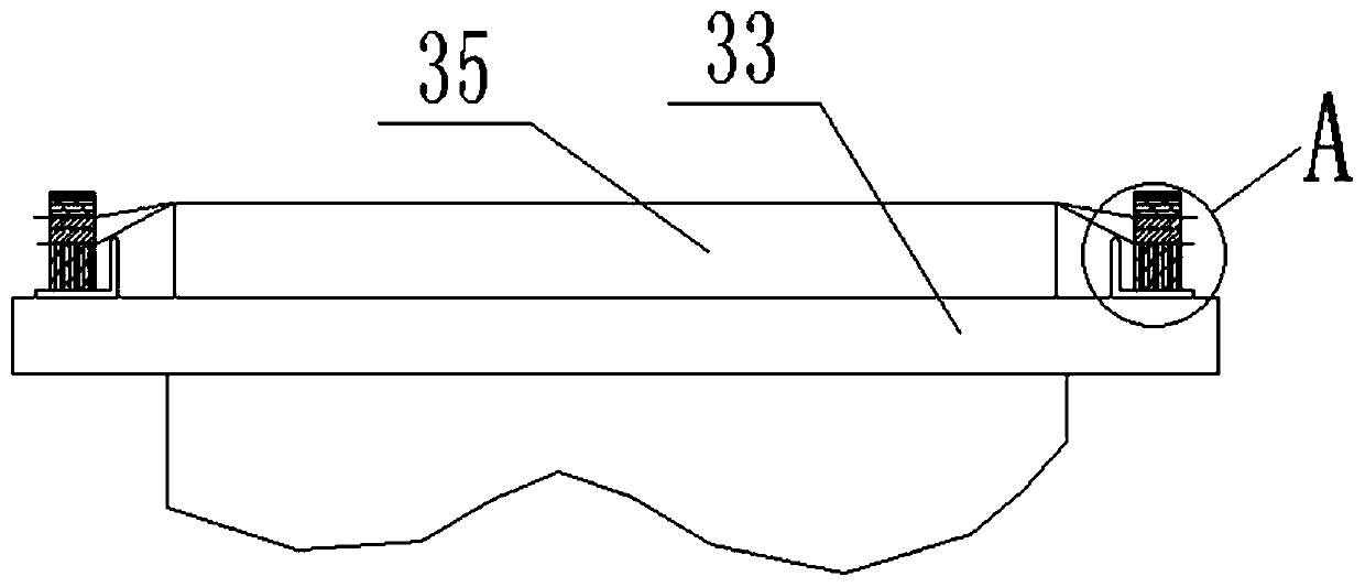
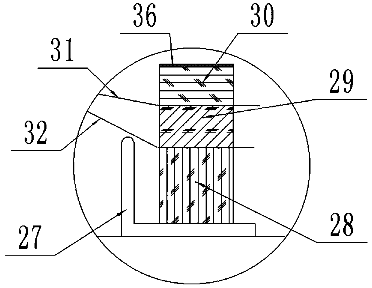
[0018] Such as Figure 1-5 As shown, an adjustable constant force screen making device includes a grid frame 25, and the grid frame 25 is sequentially provided with a first inflatable shaft 4, a second inflatable shaft 5 and a third inflatable shaft 6 from top to bottom, The two ends of the first inflatable shaft 4, the second inflatable shaft 5 and the third inflatable shaft 6 are all connected to the grid 25 through the safety chuck 7, and the grid 25 is equipped with a brake for braking the first inflatable The first magnetic powder brake 1, the second magnetic powder brake 2 and the third magnetic powder brake 3 of the torque of the shaft 4, the second air expansion shaft 5 and the third air expansion shaft 6, the right side of the grid frame 25 is fixed with a guide frame 37, the guide frame 37 The upper hinge is connected with the first upper rubber roller 8 and the second upper rubber roller 9, the first middle rubber roller 10 and the second middle rubber roller 11 are...


PUM


Abstract

The invention relates to the technical field of screen manufacturing devices, in particular to an adjustable constant-force screen manufacturing device and an application method thereof. The adjustable constant-force screen manufacturing device comprises a net rack; a guide frame is fixed to the right side of the net rack; a vulcanizing machine is fixed to the right side of the guide frame; a support plate of the vulcanizing machine is provided with a pulling device which is used for longitudinally pulling a wire screen which is connected to a PP frame in a melting way; a limiting block used for positioning the PP frame is fixed to the left side of the upper end of the support plate; and a pull-out device is fixed to the right side of the vulcanizing machine. The adjustable constant-forcescreen manufacturing device provided by the invention realizes constant-force dynamic continuous output of a coiled wire screen by virtue of a pneumatic expansion shaft, a safety chuck and a magneticpowder brake; the wire screen is horizontally pre-tightened when the wire screen is pulled; in a product manufacturing process, rubber is extruded in the longitudinal direction so that the wire screenbetween the rubber is longitudinally tensioned with deformation of the rubber and is afterwards hot-molten; pre-tightening and continuous production of the wire screen are realized in the overall manufacturing process; the production efficiency is improved; and meanwhile the pre-tensioning of the wire screen is realized as well.

Description

technical field [0001] The invention relates to the technical field of a screen making device, in particular to an adjustable constant force screen making device and a method for using the same. Background technique [0002] At present, more advanced vibrating screens mostly adopt hollow frame structure, and the screen is directly spot-welded to the frame through the pressure ring, which has simple structure, light weight and good working performance. However, during production, due to the insufficient tension of the screen, the phenomenon of screen loosening will directly affect the performance of use, especially after a period of use, the looseness of the screen will be more serious, so it has to be frequently used during use. Replacement is both troublesome and increases the cost of use. Contents of the invention [0003] The technical problem to be solved by the present invention is to stretch the wire mesh that needs to be thermally fused to the PP frame horizontally...

Claims


Application Information

Patent Timeline
Patent Type & Authority Applications(China)
IPC IPC(8): B29C65/18B29C65/44B29C65/78B29L28/00
CPCB29C65/18B29C65/44B29C65/7841B29C66/41B29L2028/00
Inventor 陈金瑞田翠平刘剑飞王小红李东胜崔士兵
Owner PUYANG ZHONGYUAN RUISHIDA PETROLEUM EQUIP CO LTD
Learn More