
Heel end anti-creeper

An anti-climber and stopper technology, applied in the field of rails, can solve the problems of affecting the axial fit of the fixing parts, cutting the fixing parts, increasing the cost, etc., and achieve the effects of improving the working conditions, reducing the stress, and increasing the contact area.

Pending Publication Date: 2019-08-16
WUHU CRSIC JIFU RAIL CO LTD
View PDF0 Cites 1 Cited by
  • Summary
  • Abstract
  • Description
  • Claims
  • Application Information

AI Technical Summary

Problems solved by technology

[0003] In order to solve the problem that if the spacer iron is used for small-numbered turnouts, it will not only increase the cost, but also affect the axial fit of the fixing parts due to the large torque, and even cut the fixing parts.

Method used


Image

  • Heel end anti-creeper
  • Heel end anti-creeper

Examples


Embodiment

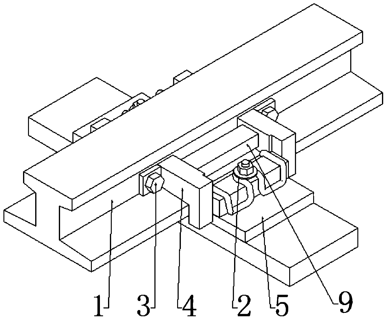
[0019] Such as Figure 1 to Figure 2 As shown, a heel anti-climbing device, the rail 1 is fixedly installed on the backing plate 5 through the fastener 2, and the backing plate 5 is connected with the switch sleeper through spike bolts, including the transverse bolt 3 and the limiter 4, There are two groups of stoppers 4, each group has two. The rail 1 is provided with a set of stoppers 4 on both sides of the backing plate 5, and each set of stoppers 4 is arranged symmetrically. Both sides of the rail 1 are connected by the transverse bolts 3 , and each limiter 4 abuts against the side of the corresponding backing plate 5 .

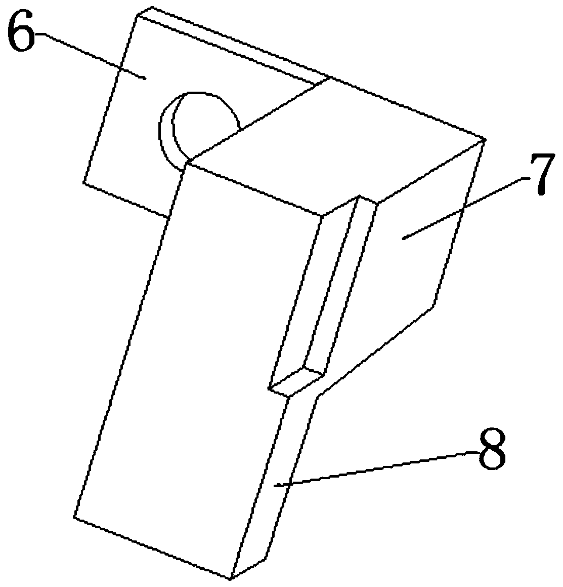
[0020] The limiter 4 includes a connecting plate 6, an intermediate body 7 and a limiting body 8, the outer side of one end of the intermediate body 7 is fixedly connected with the connecting plate 6, and the other end of the intermediate body 7 is fixedly connected with a The limiting body 8; the connecting plate 6 is provided with a through hole matche...


PUM


Abstract

The invention discloses a heel end anti-creeper and relates to the technical field of tracks. A steel rail is fixedly mounted on backing plates through fasteners; the backing plates are connected witha switch tie through track spike bolts; the heel end anti-creeper comprises transverse bolts and limiters; there are two groups of limiters; each group has two limiters; one group of limiters is arranged in positions, on the two sides of the backing plates, on the steel rail; each group of limiters is symmetrically arranged on the two sides of the steel rail and connected with each other throughthe transverse bolts; and each limiter abuts against the side surface of the corresponding backing plate. According to the heel end anti-creeper, as the limiters are mounted on the two sides of the steel rail, the distance between the steel rails do not need to be considered, the transverse bolts cannot bear very large shear force, and the axial coordination of fixing cannot be affected.

Description

technical field [0001] The invention relates to the technical field of rails; in particular, it relates to a heel anti-climbing device. Background technique [0002] The rail is a slender rod structure. When the temperature changes, a temperature force will be generated inside the rail. In order to ensure the relative position of the basic rail and the switch rail, a limit device needs to be installed at the heel of the switch rail. At present, more structures such as spacer iron are used, and because the heel support distance of small-numbered turnouts is usually larger, if the spacer iron structure is used, under a certain temperature force, the larger the force arm, the greater the torque. Therefore, the fixed parts of the spacer iron and other structures will be subjected to a large shear force, which will affect the axial fit in the slightest, and will cut off the fixed parts in severe cases, losing the fixing effect, thereby affecting the running of the train; If the ...

Claims


Application Information

Patent Timeline
IPC IPC(8): E01B13/02
CPCE01B13/02
Inventor 夏仕敏蔡韶峰疏文龙周建新
Owner WUHU CRSIC JIFU RAIL CO LTD
Learn More