Sleeve screwing device

A sleeve and driving device technology, applied in structural elements, building components, building reinforcements, etc., can solve the problems of manpower consumption, low efficiency, limited space, etc., and achieve the goal of improving screwing efficiency, high work efficiency, and saving manpower Effect

Pending Publication Date: 2019-08-16
场景美学设计(广州)有限公司
View PDF0 Cites 3 Cited by
  • Summary
  • Abstract
  • Description
  • Claims
  • Application Information

AI Technical Summary

Problems solved by technology

However, at the construction site, the number of steel bars that need to be connected is very large. The method of manually twisting the sleeve to connect the steel bars will not only cost a lot of manpower, but also be very inefficient, and the manual twisting of the sleeve will take a long time.
Moreover, the distance between adjacent steel cages is small, and there is not enough working space for tools such as general electric wrenches, which is extremely inconvenient to use.
Therefore, aiming at the problems of manpower consumption, inefficiency and limited space in the traditional way of manually twisting the sleeve to connect steel bars, the present invention discloses a sleeve screwing device

Method used


Image

  • Sleeve screwing device
  • Sleeve screwing device
  • Sleeve screwing device

Examples


Embodiment 1

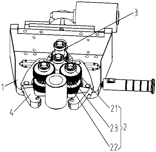
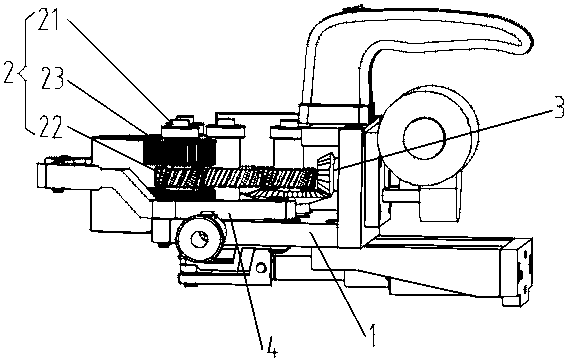
[0039] A kind of sleeve screwing device of this embodiment, such as figure 1 and figure 2 As shown, it includes a base 1, the end of the base 1 close to the sleeve is provided with a sleeve screwing device 2, and the sleeve screwing device 2 includes a driven shaft that is rotatably arranged at the end of the base 1 close to the sleeve 21, the driven shaft 21 is provided with a transmission member 22 and a roller 23; the end of the base 1 away from the sleeve is provided with a driving device 3, and the driving end of the driving device 3 is connected to the transmission member 22 in transmission ; The bottom of the base 1 is provided with a sleeve clamping device 4 corresponding to the rolling wheel 23 .

[0040] The base 1 is a hollow box-shaped frame structure, including a top plate and a bottom plate arranged in parallel. A working end plate is arranged between an end of the top plate close to the sleeve and an end of the bottom plate close to the sleeve to form a workin...

Embodiment 2

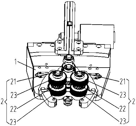
[0046] This embodiment is further optimized on the basis of embodiment 1, such as image 3 As shown, the two sides of the base 1 close to one end of the sleeve are respectively provided with sleeve screwing devices 2, and the driving device of the driving device 3 drives the sleeve screwing devices 2 on both sides at the same time, and the sleeve screwing devices 2 on both sides The sleeve screwing device 2 rotates in the same direction.

[0047] On both sides of the working end of the base 1, a sleeve screwing device 2 is respectively rotated through deep groove ball bearings, that is, a driven rotating shaft 21 is respectively rotated through deep groove ball bearings on both sides of the working end of the base 1, and Each driven shaft 21 is equipped with a transmission part 22 and a roller 23, and the transmission parts 22 on both sides are connected to the driving end of the driving device 3, that is, the driving end of the driving device 3 synchronously drives the transm...

Embodiment 3

[0050] This embodiment is further optimized on the basis of embodiment 1 or 2, such as image 3 As shown, the middle part of the driven shaft 21 is provided with a transmission member 22 , and the upper and lower sides of the driven shaft 21 are respectively sleeved with rolling wheels 23 .

[0051] The middle part of the driven shaft 21 is provided with a transmission part 22 through a flat key or an integral molding method, and roller wheels 23 are sleeved on the shaft sections of the driven shaft 21 located on both sides of the transmission part 22, that is, on the driven shaft. The upper and lower parts of 21 are provided with rolling wheels 23, the upper rolling wheels 23 are in contact with the upper outer circular surface of the sleeve, and the lower rolling wheels 23 are in contact with the lower outer circular surface of the sleeve. When rotating, the synchronous driving of the upper and lower rollers 23 can ensure the synchronous driving of the upper outer surface an...


PUM


Abstract

The invention discloses a sleeve screwing device, including a base. The end, near a sleeve, of the base is provided with the sleeve screwing device, the sleeve screwing device includes a sub-driven rotating shaft which is rotatably arranged at the end, near the sleeve, of the base, a driving part and a rolling wheel are arranged on the sub-driven rotating shaft; the end, away from the sleeve, of the base is provided with a driving device, a driving end of the driving device is connected with a driving part in a driving mode; the bottom of the base is provided with a sleeve holding device corresponding to the rolling wheel; and the device has the beneficial effects of sleeve continuous torsion, labor saving, high work efficiency, the compact structure, stable driving, large output torque and the stable rotation of the sleeve.

Description

technical field [0001] The invention belongs to the technical field of sleeve twisting devices, and in particular relates to a sleeve twisting device. Background technique [0002] When carrying out building construction, especially when carrying out the construction of large buildings such as bridges, steel bars are an important structure used to support the building, and the steel bars are usually connected to each other through sleeves. When connecting steel bars through sleeves, usually the sleeves are manually placed on the joints of the steel bars, and then manually twisted by tools such as wrenches, so that the sleeves are placed on the joints of the steel bars. However, at the construction site, the number of steel bars that need to be connected is very large, and the method of manually twisting the sleeve to connect the steel bars will not only cost a lot of manpower, but also be very inefficient, and the manual twisting of the sleeve will take a long time. Moreove...

Claims


Application Information

Patent Timeline
IPC IPC(8): E04C5/16
CPCE04C5/16
Inventor 蔡炎标陈中华唐宝宁赵榕李劲
Owner 场景美学设计(广州)有限公司
Why Eureka
Try Eureka