Eureka AIR delivers breakthrough ideas for toughest innovation challenges, trusted by R&D personnel around the world.

Furnace lining rapid pushing-out device

A push-out device, fast technology, applied in the direction of fluid pressure actuators, furnaces, furnace components, etc., can solve the problems of danger, loose bolts, and vibration during use, and achieve the effect of simple structure and safe installation

Pending Publication Date: 2019-08-16
佛山市熔科工业电炉有限公司
View PDF0 Cites 0 Cited by
  • Summary
  • Abstract
  • Description
  • Claims
  • Application Information

AI Technical Summary

Problems solved by technology

[0002] At present, the furnace lining in the industrial electric furnace and foundry equipment industry often needs to be refurbished and replaced, otherwise there will be a danger of furnace wear, but the existing furnace lining pushing device has a complicated structure, and it takes a long time and is cumbersome to install in the electric furnace process, and the installation method is usually used. The bolts are locked, and vibration will be generated during the process of pushing out the furnace lining, which will easily loosen the bolts, which is dangerous during use and threatens the safety of workers.

Method used


Image

  • Furnace lining rapid pushing-out device
  • Furnace lining rapid pushing-out device
  • Furnace lining rapid pushing-out device

Examples


Embodiment Construction

[0027] The following will clearly and completely describe the technical solutions in the embodiments of the present invention with reference to the accompanying drawings in the embodiments of the present invention. Obviously, the described embodiments are only some, not all, embodiments of the present invention. Based on the embodiments of the present invention, all other embodiments obtained by persons of ordinary skill in the art without making creative efforts belong to the protection scope of the present invention.

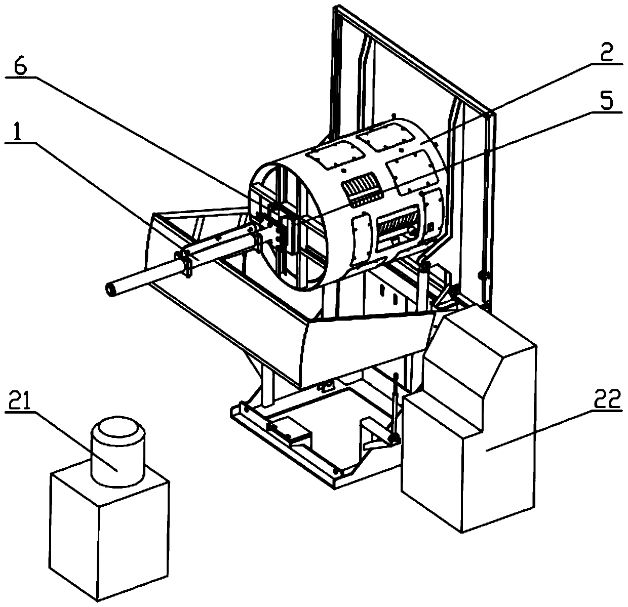
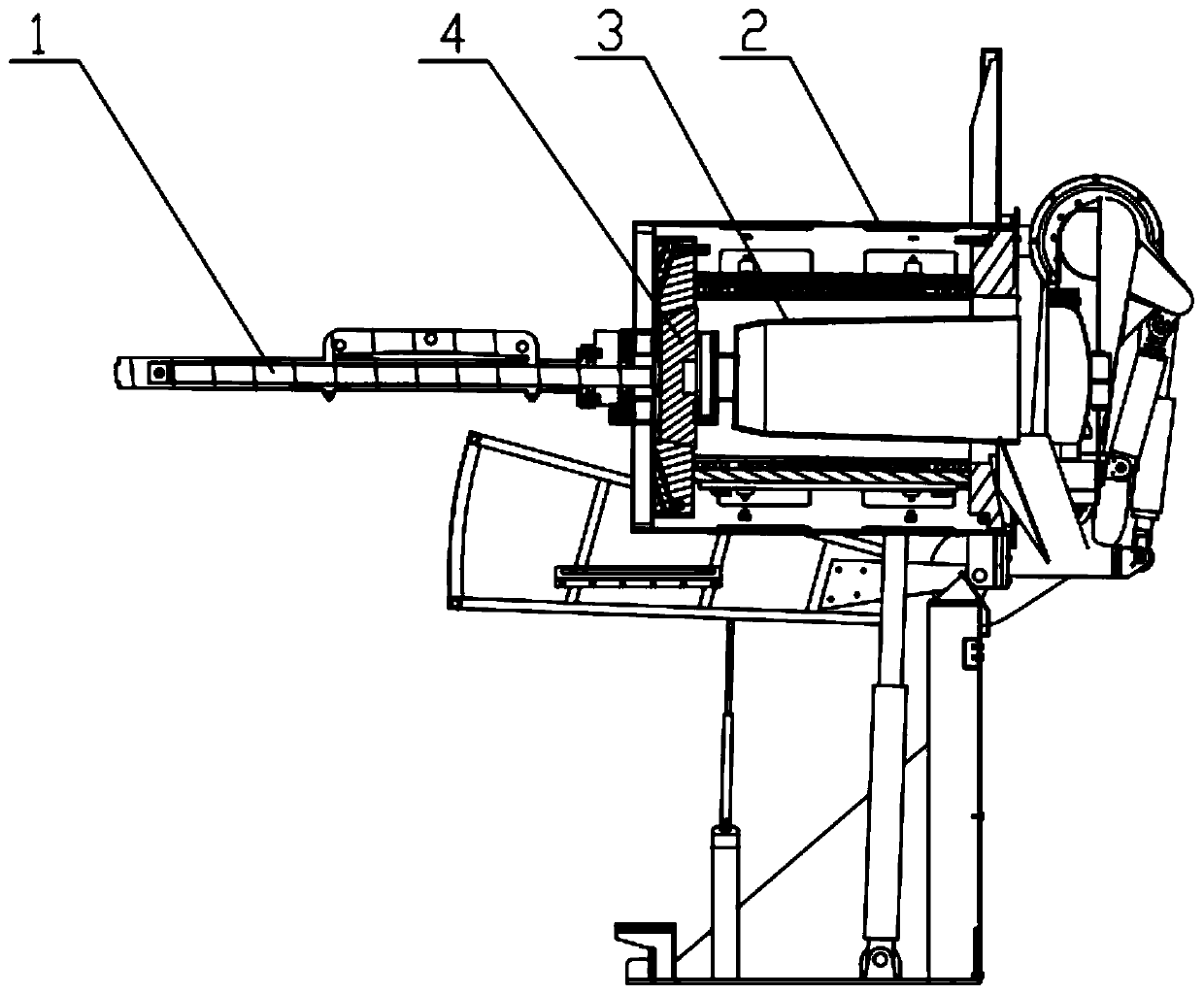
[0028] see Figure 1-6 , the present invention provides a technical solution: a furnace lining rapid push-out device, including an oil cylinder 1, an electric furnace 2, a hydraulic station 21, a furnace lining 3 arranged inside the electric furnace 2, and a pre-embedded push-out block 4 arranged at the bottom of the furnace lining 3, and a hydraulic station 21 is set on one side of the electric furnace 2, the bottom of the electric furnace 2 is provided with ...


PUM


Abstract

The invention relates to a furnace lining rapid pushing-out device. The furnace lining rapid pushing-out device comprises an oil cylinder, an electric furnace, a pre-embedded pushing-out block, a furnace lining and a hydraulic station arranged on one side of the electric furnace. The bottom of the electric furnace is provided with a mounting insertion groove. One end of the oil cylinder is provided with a clamping-in block. The mounting insertion groove comprises an electric furnace connecting plate, a U-shaped clamping base and a U-shaped limiting plate which are connected to each other. TheU-shaped limiting plate covers the side surface of the U-shaped clamping base and protrudes inwards. The clamping-in block comprises an oil cylinder connecting plate, limiting plates and insertion plates. The limiting plates are connected between the insertion plates and the oil cylinder connecting plate in an I shape. The limiting plates are symmetrically arranged on the two sides of the output end of the oil cylinder. The insertion plates cover the side surfaces of the limiting plates and protrude outwards. The oil cylinder connecting plate, the insertion plates and the electric furnace connecting plate are provided with through hole through which the output end of the oil cylinder passes. The oil cylinder connecting plate is connected with the oil cylinder. The electric furnace connecting plate is fixedly connected to the bottom of the electric furnace. A lifting plate for lifting the oil cylinder is arranged on the oil cylinder and embedded in the mounting insertion groove throughthe clamping-on block, and the fixed locking state is formed, so that the furnace lining rapid pushing-out device is simple in structure, safe and convenient to mount.

Description

technical field [0001] The invention relates to the field of electric furnace equipment, in particular to a furnace lining rapid push-out device. Background technique [0002] At present, the furnace lining in the industrial electric furnace and foundry equipment industry often needs to be refurbished and replaced, otherwise there will be a risk of furnace wear. When the bolts are locked, vibration will be generated during the process of pushing out the furnace lining, which will easily loosen the bolts, which will be dangerous during use and threaten the safety of workers. Contents of the invention [0003] In order to overcome the current defects of electric furnace equipment, the object of the present invention is to provide a furnace lining quick push-out device with simple structure, safety and quick installation. [0004] The technical scheme adopted in the present invention is: [0005] A furnace lining rapid push-out device, including an oil cylinder, an electric...

Claims


Application Information

Patent Timeline
IPC IPC(8): F15B15/14B66C1/10F27D1/16
CPCF15B15/14B66C1/10F27D1/16F27D2001/1605
Inventor 彭一波彭益树
Owner 佛山市熔科工业电炉有限公司
Why Eureka
Eureka Blog
Learn More