
Gear

A gear, gear body technology, applied to gears. It can solve problems such as affecting the stability of gear meshing, easy interference of teeth, reducing bending strength of teeth on gears, etc., to achieve the effect of increasing installation stability

Inactive Publication Date: 2019-08-16
薛江波
View PDF0 Cites 2 Cited by
  • Summary
  • Abstract
  • Description
  • Claims
  • Application Information

AI Technical Summary

Problems solved by technology

[0004] In order to make up for the deficiencies of the prior art, the present invention proposes a gear, which is mainly used to solve the existing involute gears used in special environments, when the number of teeth of the involute gears meshing with each other is small , the intermeshed teeth are prone to interference, which reduces the bending strength of the upper teeth of the gear and affects the stability of the gear mesh.

Method used


Image

  • Gear
  • Gear
  • Gear

Examples


Embodiment Construction

[0020] use Figure 1-Figure 3 A gear according to one embodiment of the present invention will be described below.

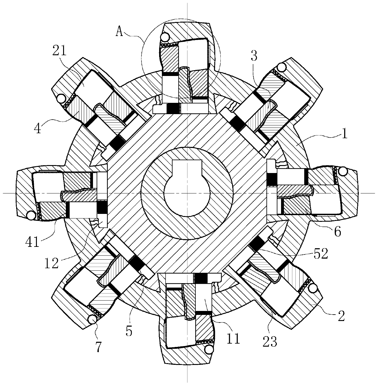
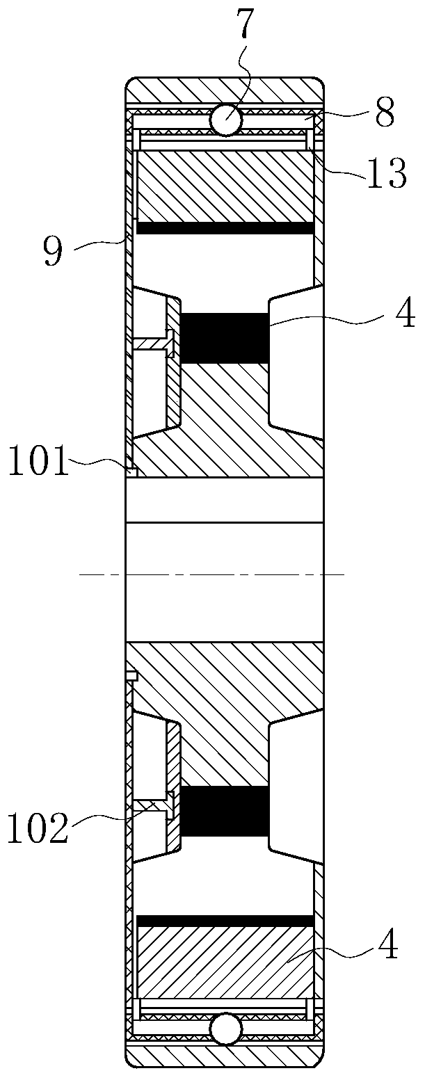
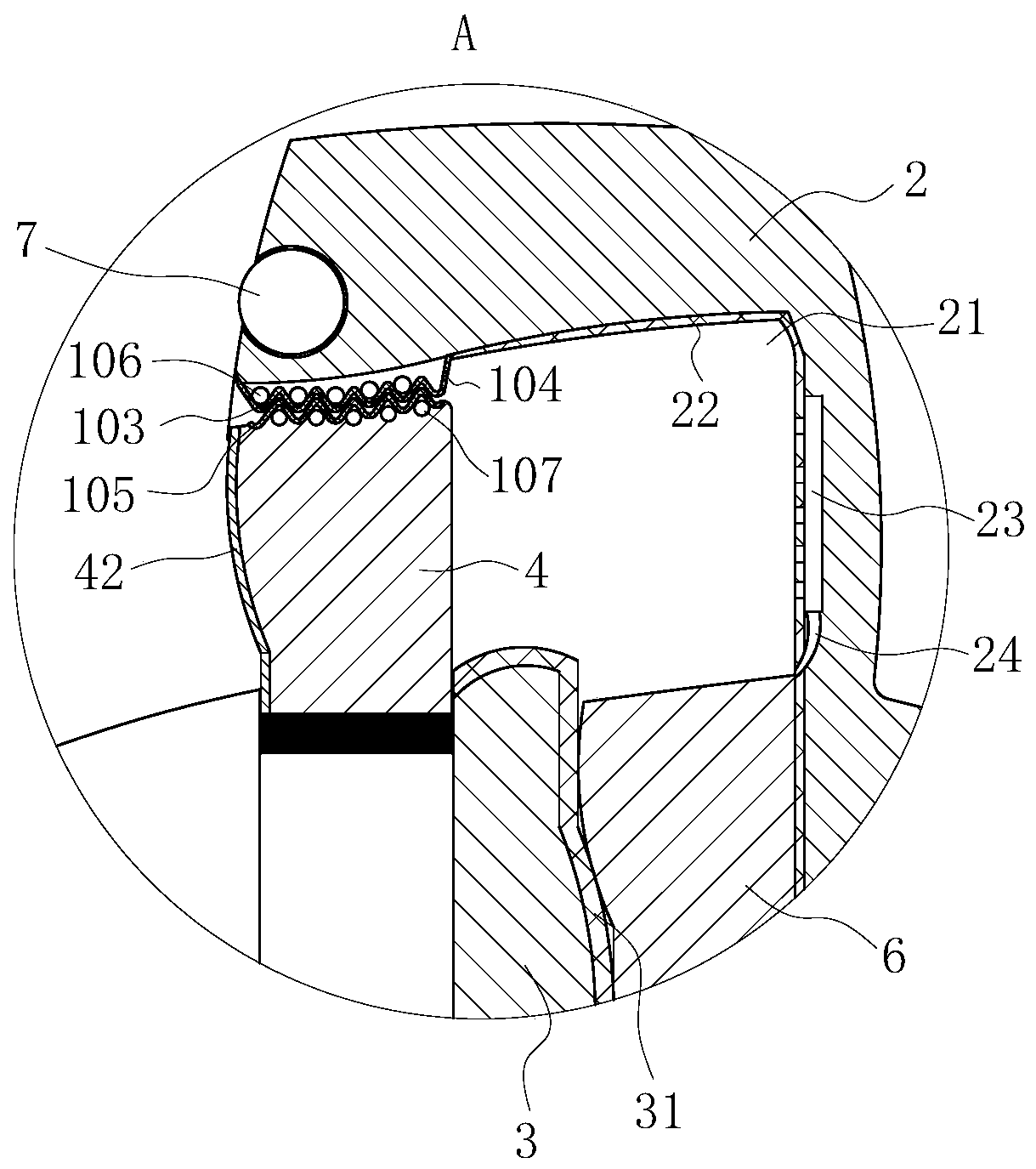
[0021] Such as figure 1 , figure 2 and image 3As shown, a gear of the present invention includes a gear body 1; the gear body 1 is evenly provided with teeth 2; it is characterized in that: the gear body 1 is uniformly provided with a sliding cavity 11, and the sliding cavity 11 are provided with a partition plate 3; the inside of the teeth 2 is provided with a sliding groove 21, and the sliding groove 21 communicates with the sliding chamber 11; a friction block 4 is arranged in one side of the sliding groove 21, and the friction block The bottom end of the 4 is provided with a magnet layer 41, and the outer surface of the friction block 4 is provided with an arc-shaped wear-resistant layer 42; the friction block 4 is inserted into the sliding cavity 11, and the width of the bottom end of the friction block 4 is equal to that of the barrier block and the ...


PUM


Abstract

The invention belongs to the technical field of gears, and particularly relates to a gear. The gear comprises a gear body, wherein teeth are uniformly arranged on the gear body, sliding cavities are uniformly formed in the gear body, a partition baffle is arranged in each sliding cavity, sliding grooves are formed in the teeth, friction blocks are arranged in one sides of the sliding grooves, magnet layers are arranged at the bottom ends of the friction blocks, arc-shaped wear-resistant layers are arranged on the outer side surfaces of the friction blocks, the friction blocks are inserted intothe sliding cavities, the width of the bottom end of each friction block is equal to the distance between the corresponding partition baffle and the side wall of the corresponding sliding cavity, andthe other side surfaces of the partition baffles are in contact with standby blocks. According to the gear, the friction blocks and the standby blocks are arranged, the friction blocks and the standby blocks are correspondingly arranged in the sliding cavities, then the arranged friction blocks and the arranged standby blocks can be used for improving the wear resistance of the teeth, then the degree of abrasion between the teeth on the mutually meshed gears is reduced, and then the bending strength of the teeth on the involute gear and the meshing stability between the teeth are improved.

Description

technical field [0001] The invention belongs to the technical field of gears, in particular to a gear. Background technique [0002] Gear is one of the transmission parts widely used in machines. It can transmit power and change the speed and direction of rotation. There are many types of gears, which can be divided into three categories according to their transmission forms: cylindrical gears, bevel gears, and worm gears. Worm; involute cylindrical gear is a kind of gear. When the tooth shape of the gear is composed of involute and transition line, it is called involute gear. [0003] However, in the existing involute gears, the involute gears used in special environments, when the number of teeth of the involute gears meshing with each other is small, the teeth of the meshing teeth are prone to interference, thereby reducing the number of teeth on the gears. The bending strength of the teeth also affects the stability of the meshing of the gears. Contents of the inventi...

Claims


Application Information

Patent Timeline
Patent Type & Authority Applications(China)
IPC IPC(8): F16H55/08F16H55/12F16H55/17
CPCF16H55/0806F16H55/12F16H55/17F16H2055/175
Inventor 不公告发明人
Owner 薛江波
Learn More