Switching valve for prolonging response time
A response time, valve opening and closing technology, applied in sliding valves, valve devices, engine components, etc., can solve the problems of uncontrollable response time, increase response time, and fast opening and closing valve response time, so as to ensure accuracy and avoid energy. Impact, improve service life effect
- Summary
- Abstract
- Description
- Claims
- Application Information
AI Technical Summary
Problems solved by technology
Method used
Image

Examples
Embodiment 1
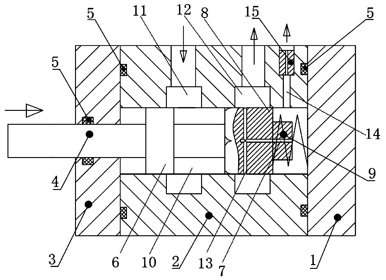
[0015] Embodiment 1, a kind of switch valve that increases response time, as figure 1 As shown, it includes a valve body 2, the valve body 2 is provided with a hydraulic passage 10 and an oil inlet 11 and an oil outlet 12 communicating with the hydraulic passage 10, and the two ends of the hydraulic passage 10 are respectively provided with an end cover 3 and a bottom plate 1. Hydraulic oil can enter the hydraulic channel 10 of the valve body 2 through the oil inlet 11 , and then flow into the connected hydraulic system through the oil outlet 12 . Sealing rings 5 are provided between the valve body 2 and the end cover 3 and between the valve body 2 and the bottom plate 1 to effectively avoid oil leakage.
[0016] A spool 4 is movable through the end cover 3 and is movably plugged with the hydraulic passage 10. A sealing ring 5 is provided between the spool 4 and the end cover 3, which effectively ensures that the spool 4 slides along the hydraulic passage 10. sealing perfor...
Embodiment 2
[0018] Embodiment 2, an on-off valve with increased response time, the oil inlet 11 is set close to the end cover 3, the oil outlet 12 is set close to the bottom plate 1, and the end of the valve core 4 close to the bottom plate 1 is set with the bottom plate 1 back-moving spring 9 connected at the top. One end of the return spring 9 is sheathed on the valve core 4 and abuts against the rear end surface of the delay response piston 8 , and the other end of the return spring 9 abuts against the inner end surface of the bottom plate 1 .
[0019] When no external force acts on the spool 4, the small radial hole 13 is located between the oil inlet 11 and the oil outlet 12 under the action of the return spring 9, and the oil inlet 11 and the oil outlet 12 cannot Connected, the switch valve is closed. When the spool 4 is squeezed by external force, the return spring 9 shrinks, and the radial small-diameter hole 13 communicates with the oil outlet 12, and the pressure in the hydraul...
Embodiment 3
[0021] Embodiment 3, a switch valve with increased response time, the axial small-diameter hole 7 is a through hole through the delay response piston 8, and the high-pressure oil in the oil inlet 11 can flow into the cavity where the return spring 9 is located through the through hole body, thereby providing damping.
[0022] The valve body 2 is provided with an oil return port 14 which communicates with the hydraulic channel 10 and is located between the delay response piston 8 and the bottom plate 1, and the oil return port 14 is provided with a damping plug 15 for controlling the oil return rate , The damping plug 15 is provided with a throttling channel connected to the oil return port. By changing the size of the throttling channel of the damping plug 15, the magnitude of the damping provided can be controlled, thereby conveniently adjusting the speed of the response time.
[0023] Other structures of this embodiment are the same as those of Embodiment 2.
PUM
 Abstract
Description
Claims
Application Information
 - Generate Ideas
- Intellectual Property
- Life Sciences
- Materials
- Tech Scout
- Unparalleled Data Quality
- Higher Quality Content
- 60% Fewer Hallucinations
Browse by: Latest US Patents, China's latest patents, Technical Efficacy Thesaurus, Application Domain, Technology Topic, Popular Technical Reports.
© 2025 PatSnap. All rights reserved.Legal|Privacy policy|Modern Slavery Act Transparency Statement|Sitemap|About US| Contact US: help@patsnap.com