Supercharge Your Innovation With Domain-Expert AI Agents!

Special-purpose vehicle distributed control method and system based on CAN bus

A CAN bus and distributed control technology, applied in the field of CAN bus, can solve the problems of occupying a large amount of controller resources, complex electrical wiring harness, unfavorable maintenance, etc., to reduce ports and electrical connection harnesses, improve work efficiency, and reduce conversion paths. Effect

Inactive Publication Date: 2019-08-16
湖南广大机电有限公司
View PDF2 Cites 2 Cited by
  • Summary
  • Abstract
  • Description
  • Claims
  • Application Information

AI Technical Summary

Problems solved by technology

[0004] The invention provides a CAN bus-based distributed control method and control system for special vehicles, which are used to overcome the defects in the prior art that occupy a large amount of controller resources, complicate the electrical wiring harness, and are not conducive to maintenance, and reduce the cost and volume of the controller. , simplified electrical wiring harness, easy maintenance

Method used


Image

  • Special-purpose vehicle distributed control method and system based on CAN bus
  • Special-purpose vehicle distributed control method and system based on CAN bus
  • Special-purpose vehicle distributed control method and system based on CAN bus

Examples


Embodiment 1

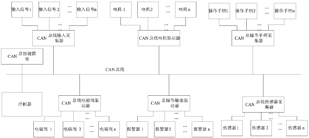
[0029] Please refer to figure 1 , figure 2 , in one embodiment of the present invention, the distributed control method of special vehicle based on CAN bus, comprises the following steps:

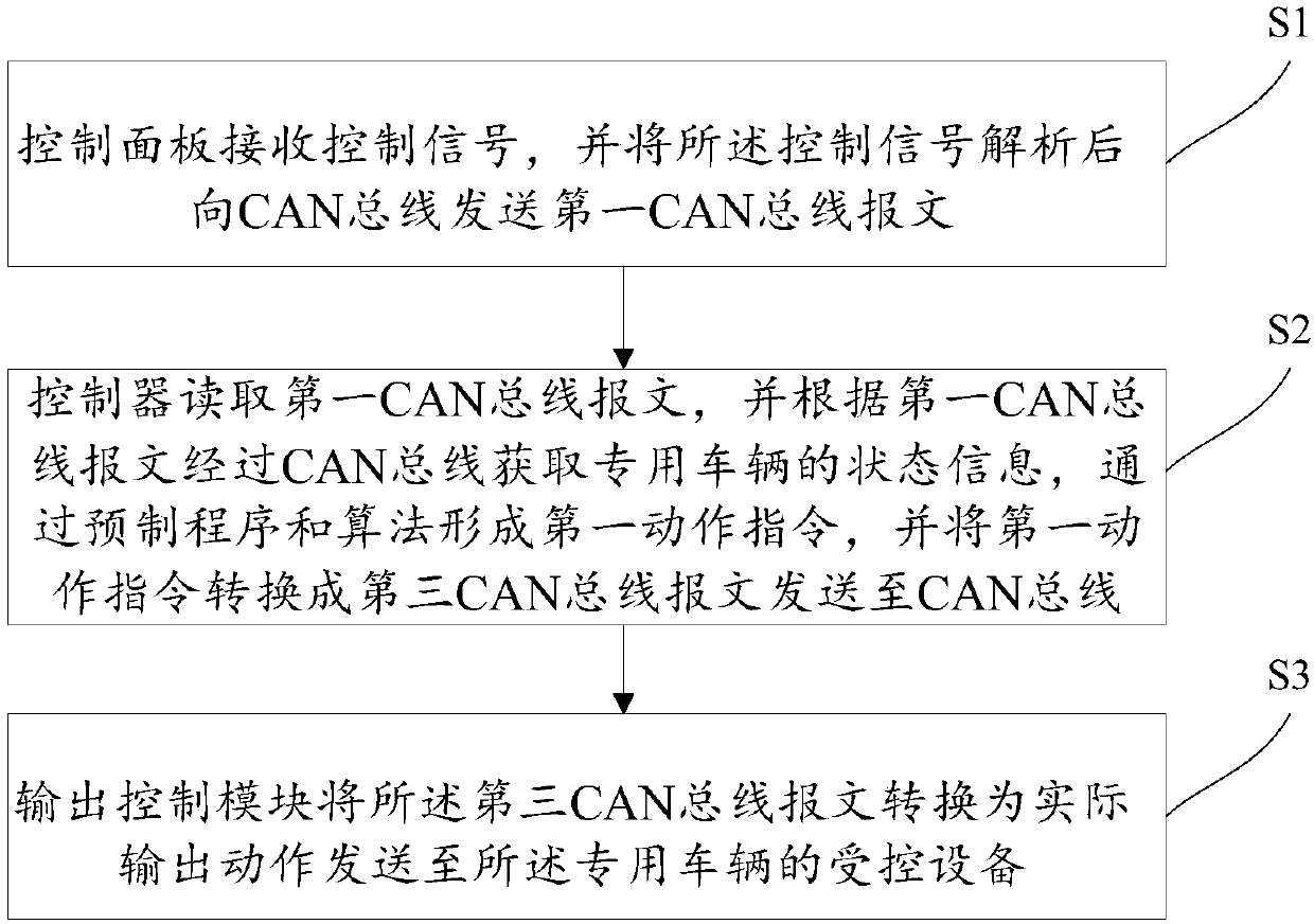
[0030] Step S1, the control panel receives the control signal, and sends the first CAN bus message to the CAN bus after analyzing the control signal;

[0031] The control signal here can be the level signal sent by the button circuit, or the click signal sent by the mouse, or the analog signal sent by the operating handle. After the main control module analyzes the above level signal or analog signal, it forms the first The CAN bus message is sent to the CAN bus, and the ID number of the first CAN bus message is used to indicate the specific device to be controlled. In one embodiment of the present invention, the angle of the first valve of the vehicle is controlled to be adjusted to 90 degrees through the buttons on the control panel.

[0032] Step S2, the controller reads the first CA...

Embodiment 2

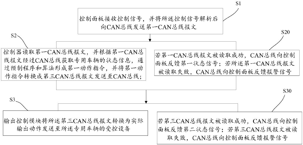
[0038] see image 3 , the step S2 also includes:

[0039] Step S20, if the first CAN bus message is read successfully, the CAN bus feeds back the first status signal to the control panel; if the first CAN bus message is read unsuccessfully, the CAN bus sends the control panel a Panel feedback alarm signal;

[0040] As an embodiment of the present invention, the control panel also has an indicator light and an alarm. After pressing the first control button, the main control module sends the first CAN bus message to the CAN bus, and the controller reads successfully, and the first indicator light It starts to flash, the reading fails, and the alarm sounds.

[0041] The step S3 also includes:

[0042] Step S30, if the third CAN bus message is successfully read, the CAN bus feeds back a second status signal to the control panel; if the third CAN bus message is read unsuccessfully, the CAN bus sends the control panel a The panel feeds back the alarm signal.

[0043] The output a...

Embodiment 3

[0045] see Figure 4 , in an embodiment of the present invention:

[0046] Step S1 further includes: the sensor collection module converts the physical signal collected by the sensor into a second CAN bus message containing the state information of the special vehicle and sends it to the CAN bus.

[0047] The physical signals here include current signals, voltage signals, switch signals, analog signals, etc. The status information of the vehicle includes the position of the vehicle, the height of the components, the opening and closing state, the extension length, etc. This series of information can be passed through the sensor After detecting and transmitting, the controller obtains these data through the CAN bus, and calculates and obtains the actions of each control component as parameters.

[0048] Also include after step S3:

[0049] Step S4, the display module reads the second CAN bus message, and converts the second CAN bus message into visual data for presentation. ...


PUM


Abstract

The invention discloses a special-purpose vehicle distributed control method and system based on a CAN bus. The method comprises the steps that a control panel receives a control signal, analyzes thecontrol signal and then sends a first CAN bus message to the CAN bus; a controller reads the first CAN bus message, acquires state information of a special-purpose vehicle through the CAN bus according to the first CAN bus message, forms a first action instruction through a preset program and an algorithm, converts the first action instruction into a third CAN bus message and sends the third CAN bus message to the CAN bus; and an output control module converts the third CAN bus message into an actual output action and sends the actual output action to a controlled device of the special-purposel vehicle. Through the control method and system, the problems that in the prior art, a large quantity of controller resources are occupied, an electrical harness is complicated, and maintenance is not benefited are solved.

Description

technical field [0001] The invention relates to the field of CAN bus technology, in particular to a CAN bus-based distributed control method and control system for special purpose vehicles. Background technique [0002] At present, centralized control is usually used in the control of special vehicles. The input signals of the operation module, display data, and the acquisition signals of the sensors on the vehicle need to be connected to the controller, and the controller detects the state of the input device; The controller collects, converts and processes the signal of the sensor, and then outputs the signal to the controlled device through the set logic program; the data to be displayed is also processed by the controller and sent to the display for display; all devices need to be connected The controller can work normally, and the signals of all devices need to be processed by the controller before reaching other devices. [0003] The above-mentioned centralized contro...

Claims


Application Information

Patent Timeline
IPC IPC(8): G05B23/02
CPCG05B23/0213G05B2219/24065
Inventor 姜鹏朱小明
Owner 湖南广大机电有限公司
Features
  • R&D
  • Intellectual Property
  • Life Sciences
  • Materials
  • Tech Scout
  • Unparalleled Data Quality
  • Higher Quality Content
  • 60% Fewer Hallucinations
Learn More