Reinforcing structure of anti-falling-type indication pile base

A technology for strengthening structures and marking piles, which is applied in the direction of marking, display devices, instruments, etc., can solve problems such as knockdown, tilting, small area, etc., and achieve high connection strength and ideal anti-fall effect

Inactive Publication Date: 2019-08-16
PINGDINGSHAN POWER SUPPLY ELECTRIC POWER OF HENAN
View PDF15 Cites 1 Cited by
  • Summary
  • Abstract
  • Description
  • Claims
  • Application Information

AI Technical Summary

Problems solved by technology

However, this utility model still does not solve the problem that the base of the marking pile adopts a common bas

Method used


Image

  • Reinforcing structure of anti-falling-type indication pile base
  • Reinforcing structure of anti-falling-type indication pile base
  • Reinforcing structure of anti-falling-type indication pile base

Examples


Embodiment 1

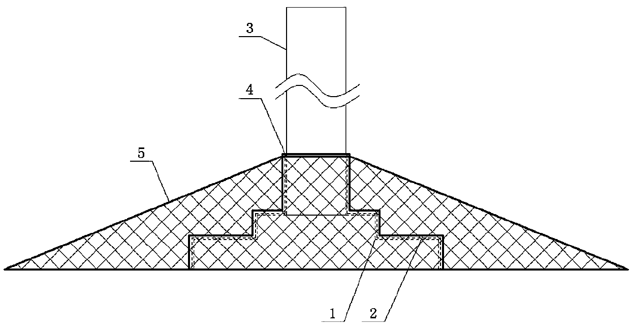
[0030] Such as figure 1 As shown, an anti-falling type marking pile base reinforcement structure includes a base sleeve 2 whose shape matches the marking pile base 1 and is used to cover the marking pile base 1. The top of the base sleeve 2 is opened to allow the marking The perforation 4 pierced by the pile part 3, the base sleeve 2 is provided with a hollow and flat grid plate cover 5, and the grid plate cover 5 covers the base sleeve 2 inside.

[0031] The grid plate cover 5 and the base sleeve 2 are integrally formed.

[0032] In this embodiment, the connection structure between the grid plate cover and the base sleeve can adopt an integrated molding structure according to different materials. When both the grid plate cover and the base sleeve are made of plastic parts, it can be made by integral plastic molding technology. Integral molding structure, when both the grid plate cover and the base sleeve are made of concrete parts, the integrated casting technology can be us...

Embodiment 2

[0034] The difference from Embodiment 1 is that the grid plate cover 5 and the base sleeve 2 are connected by an assembled structure.

[0035] The assembled structure adopted between the grid plate cover 5 and the base sleeve 2 is a bolt and nut assembly connection structure, that is, an extension part is arranged on the grid plate cover and the base sleeve, and between the two extension parts Connections are made by bolt and nut assemblies.

[0036] In this embodiment, the bolt and nut assembly connection structure is used to realize the assembled structure design between the grid plate cover and the base sleeve. Of course, the hook and ring connection structure or the screw connection structure can also be used to achieve the same effect; when using When the hook and ring connection structure is used, a hook / hanging ring is set on the grid plate cover and a hanging ring / hook matching the hook is set on the base sleeve. The internal thread is provided, and the external threa...

Embodiment 3

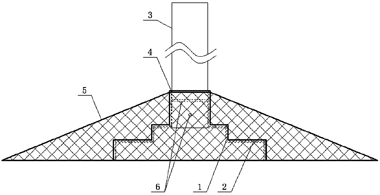
[0038] Such as figure 2 As shown, an anti-falling type marking pile base reinforcement structure includes a base sleeve 2 whose shape matches the marking pile base 1 and is used to cover the marking pile base 1. The top of the base sleeve 2 is opened to allow the marking The perforation 4 pierced by the pile part 3, the base sleeve 2 is provided with a hollow and flat grid plate cover 5, and the grid plate cover 5 covers the base sleeve 2 inside.

[0039] The grid plate cover 5 and the base sleeve 2 are integrally formed.

[0040] An insertion hole 6 is horizontally opened on the base sleeve 2 .

[0041] The number of the jacks 6 is 2 which are spatially staggered.

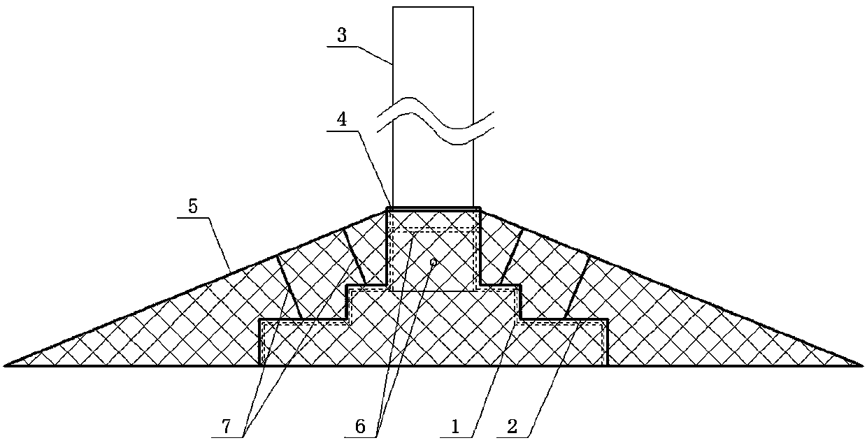
[0042] When the marking pile has no base, use a drilling rig to drill a through hole that matches the socket 6 on the marking pile, and use the fixing rod to penetrate the socket 6 and the through hole in order to fix the marking pile on the base cover Inside barrel 2.

[0043] Both the base sleeve 2 and the gr...


PUM


Abstract

The invention discloses a reinforcing structure of an anti-falling-type indication pile base. The reinforcing structure comprises a base sleeve with the shape matched with the indication pile base, the base sleeve is used for sleeving the indication pile base, a penetrating hole allowing an indication pile rod part to penetrate out is formed in the top of the base sleeve, and a hollowed-out flat grid plate cover is arranged on the outer portion of the base sleeve and sleeves the base sleeve. According to the reinforcing structure, the hollowed-out flat grid plate cover is utilized, and on onehand, the area of the part, buried in the ground, of an indication pile can be increased to ensure that when external force is applied to the indication pile, the indication pile is not easily inclined or pushed over; on the other hand, the rhizomes of green plants can penetrate through hollowed-out grids of the grid plate cover and do not influence growth of the green plants above the rhizomes.

Description

technical field [0001] The invention belongs to the technical field of road pipeline marking piles, in particular to an anti-falling type marking pile base reinforcement structure. Background technique [0002] Pipeline marking piles indicate that there are corresponding pipelines under the marking piles. At present, domestic electricity, communications, gas, and heat are widely used. The marking piles are currently divided into marking piles laid in the green belt and marking piles laid on the road. The marking piles in the green belt should stand upright directly above the pipeline under normal circumstances, but the marking piles are often tilted or placed upside down due to reasons such as landscaping, road expansion, and passer-by damage. The piles are easy to be covered and buried by earth, stones and low bushes, which can not play the due warning function, and the marking piles covered by earth, stones and low bushes will be eroded and eventually discarded as a stone,...

Claims


Application Information

Patent Timeline
IPC IPC(8): G09F7/18
CPCG09F7/18
Inventor 郭姚超王伟利殷红德孙世勇王逸超王得民叶茂程龙李伟东马文恒赵宇丹郭丽丽
Owner PINGDINGSHAN POWER SUPPLY ELECTRIC POWER OF HENAN
Why Eureka
Try Eureka