SR configuration method, network side equipment and terminal side equipment

A network-side device and configuration method technology, applied in the field of communication, can solve problems such as delay, UE performance is greatly affected, and SR delay is increased, so as to achieve the effects of reducing delay, ensuring performance, and increasing availability

Active Publication Date: 2019-08-16
VIVO MOBILE COMM CO LTD
View PDF3 Cites 3 Cited by
  • Summary
  • Abstract
  • Description
  • Claims
  • Application Information

AI Technical Summary

Problems solved by technology

When the SFI indicates that the configured SRopportunity is not available, the transmission of the SR needs to be postponed until the next possible transmission time, which will increase the delay of the SR transmission, especially when the SR period itself is relatively small, because the UE needs to The delay requirement is relatively high, and delaying sending SR will have a great impact on UE performance

Method used


Image

  • SR configuration method, network side equipment and terminal side equipment
  • SR configuration method, network side equipment and terminal side equipment
  • SR configuration method, network side equipment and terminal side equipment

Examples


specific Embodiment 1

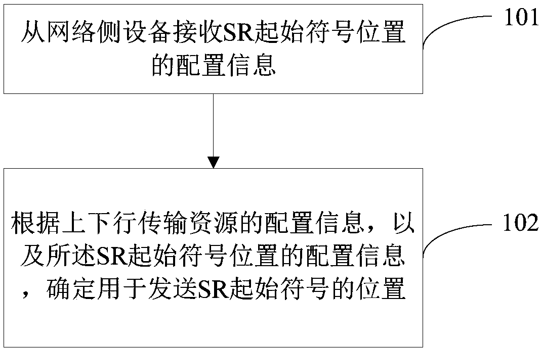
[0102]In this embodiment, the Semi-Static UL-DL configuration takes M slots as a cycle, and the symbols of each slot can be configured. Each slot can include DL symbols, UL symbols, and unknown symbols. Different slots in the M slots There may be different configurations.

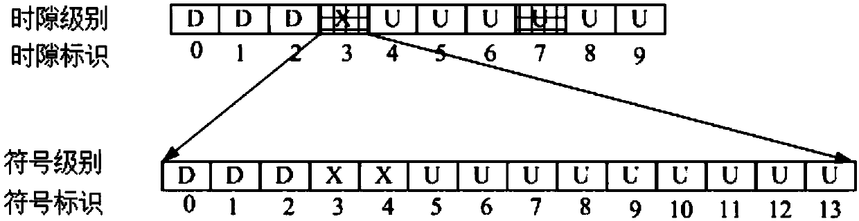
[0103] Such as image 3 As shown, the UL-DL configuration cycle is 10 slots, the first three slots are DL symbols, the fourth slot contains the switching point from DL to UL, and the subsequent slots are all UL symbols, as shown in the figure Use D to represent the DL symbol, X to represent the unknown symbol, and U to represent the UL symbol. The slot for sending the SR may be notified to the UE through bitmap1 of a slot-level (Slot-level), that is, the first bitmap. Among them, the number of bits in bitmap1 is related to the UL-DL configuration, and the length S of bitmap1 can take the following two values ​​but is not limited to the following values:

[0104] (1) The length S of bitmap1 is equal to th...

specific Embodiment 2

[0125] In this embodiment, Semi-Static UL-DL configuration can configure the symbols of each slot, and each slot can include DL symbols, UL symbols and unknown symbols.

[0126] Such as Figure 4 As shown, a slot includes 14 symbols, the first four symbols are DL symbols, the fifth-seventh symbols are unknown symbols, and the last seven symbols are all UL symbols. In the figure, D represents DL symbol and X represents unknown symbol, U to represent the UL symbol.

[0127] Which symbols in the slot are used to send the SR can be indicated through Symbol-level bitmap3, that is, the third bitmap, that is, SR transmission occassion. Among them, the length L of bitmap3 can take one or more of the following values:

[0128] (1) The length L of bitmap3 is equal to the number K of symbols included in a time slot;

[0129] (2) The length L of bitmap3 is equal to the number k of uplink symbols and / or unknown symbols included in a time slot;

[0130] (3) The length L of bitmap3 is eq...


PUM


Abstract

The invention provides an SR configuration method, network side equipment and terminal side equipment, and belongs to the technical field of communication. The SR configuration method applied to terminal side equipment comprises the following steps: receiving configuration information of an SR initial symbol position from network side equipment; and determining the position for sending the SR initial symbol according to the configuration information of the uplink and downlink transmission resources and the configuration information of the SR initial symbol position. According to the technicalscheme provided by the invention, the SR sending resources can be configured by combining the configuration information of the uplink and downlink resources; and the situation that the configured SR opportunity is unavailable is reduced / the situation that the SR opportunity is available is increased, so that the reduction of the SR sending time delay is facilitated, and the performance of the UE is ensured.

Description

technical field [0001] The present invention relates to the technical field of communications, and in particular to an SR configuration method, network side equipment, and terminal side equipment. Background technique [0002] When the terminal side equipment, such as user equipment (user equipment, UE) has uplink services to send and there are no uplink shared channel (uplink shared channel, UL-SCH) resources, it sends a scheduling request (Scheduling Request, SR) to the base station to request UL -Sch. Since the SR is sent when there is no UL-SCH resource, the SR is sent on the Physical Uplink Control Channel (PUCCH), and the SR can only be configured in the Radio Resource Control (RRC) sent on the resource. The SR configuration method in the prior art is to use the RRC configuration information to configure the SR period and offset value to determine the resource location where the SR may be transmitted. [0003] In the NR unpaired spectrum (NR unpaired spectrum) / Time ...

Claims


Application Information

Patent Timeline
Patent Type & Authority Applications(China)
IPC IPC(8): H04L5/00H04W72/04
CPCH04W72/0446H04L5/0053H04W72/20
Inventor 李娜沈晓冬潘学明鲁智
Owner VIVO MOBILE COMM CO LTD
Why Eureka
Try Eureka