

Rotor for rotary electric machine
A technology of rotating electrical machines and rotors, which is applied in the field of rotors for rotating electrical machines to achieve the effect of realizing width
- Summary
- Abstract
- Description
- Claims
- Application Information
AI Technical Summary
Problems solved by technology
Method used
Image

Examples
Embodiment Construction
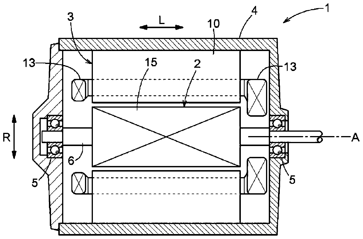
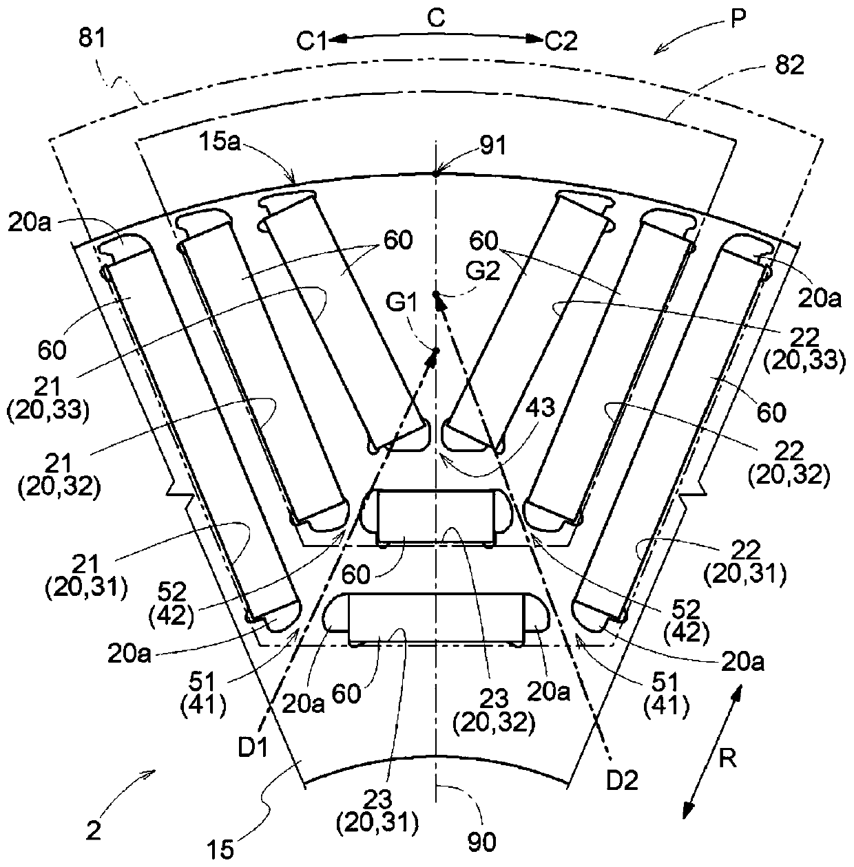
[0029] Embodiments of a rotor for a rotating electric machine will be described with reference to the drawings. In addition, in the following description, the axis A (refer to figure 1 ) is defined as a benchmark. The axis A is an imaginary axis, and the rotor 2 rotates around the axis A. Additionally, if figure 2 As shown, one side in the circumferential direction C is referred to as "the first side in the circumferential direction C1", and the other side in the circumferential direction C (the side opposite to the first side in the circumferential direction C1) is referred to as "the second side in the circumferential direction C2". ". In this specification, terms such as dimensions, arrangement directions, arrangement positions, etc. are used as concepts including states including differences due to errors (errors to a degree acceptable in manufacturing).
[0030] Such as figure 1 As shown, the rotor 2 is a rotor for a rotating electrical machine, and is used for the...
PUM
 Abstract
Description
Claims
Application Information