Equipment automatic loading deviation identification method and system based on three-dimensional laser radar

A technology of automatic loading and identification method, which is applied in the direction of radio wave measurement system, measurement device, electromagnetic wave re-radiation, etc., can solve the problems of complex layout, heavy workload, and great difficulty, so as to reduce loading workload and improve loading efficiency , the effect of high degree of intelligence

Pending Publication Date: 2022-05-10
ARMY ENG UNIV OF PLA
View PDF2 Cites 0 Cited by
  • Summary
  • Abstract
  • Description
  • Claims
  • Application Information

AI Technical Summary

Problems solved by technology

However, when the vehicle equipment is loaded and running, since the railway platform is generally in the blind spot of the driver, it is difficult to meet the requirements of the specification for the distance between the center of gravity of the vehicle and the center of the railway platform of the train. It takes more than ten minutes for experienced drivers and guides to accurately complete the loading task of a large vehicle
[0003] Therefore, there are many patented technologies about this application. The patent CN204323334U proposes a railway loading guidance system for armored vehicles, which uses infrared depth vision sensors, global positioning modules, ultrasonic ranging sensors and high-definition color cameras. A railway loading guidance system for armored vehicles has been developed, but there are problems of high cost, large errors and complex layout, and it is impossible to realize automatic loading and driving of vehicles, and the stability cannot be guaranteed by using wireless methods
The utility model patent CN206695796U discloses a guiding device for railway loading vehicles, which uses an image sensor to identify the center line to realize guided loading. It is necessary to lay the center line of the railway slab in advance.

Method used


Image

  • Equipment automatic loading deviation identification method and system based on three-dimensional laser radar
  • Equipment automatic loading deviation identification method and system based on three-dimensional laser radar
  • Equipment automatic loading deviation identification method and system based on three-dimensional laser radar

Examples


Embodiment 1

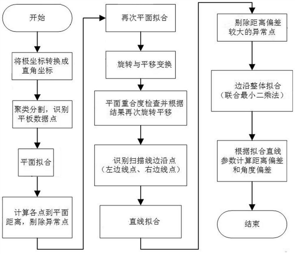
[0061] A three-dimensional lidar-based automatic loading deviation identification method for equipment, including: scanning the area where the railway platform is located, obtaining the original point cloud data and performing preprocessing; clustering and segmenting the preprocessed original point cloud data, and identifying the railway platform Data points; carry out plane fitting on railway plate data points to obtain a three-dimensional fitting plane; transform the three-dimensional fitting plane into a two-dimensional fitting plane through rotation and translation transformation; simultaneously Perform straight line fitting to obtain the parameters of the straight line, and then calculate and obtain the automatic loading deviation of the equipment.

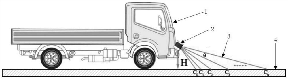
[0062] Such as figure 1 As shown, the present embodiment takes the use of railway flat-bed transfer vehicles as an example for illustration, figure 1 The medium vehicle 1 needs to travel on the railway platform 4 to the cent...

Embodiment 2

[0146] Based on the three-dimensional lidar-based automatic loading deviation recognition method for equipment described in Embodiment 1, this embodiment provides a three-dimensional laser radar-based automatic equipment loading deviation recognition system, including: a data acquisition module for scanning railway flat panels In the area where the original point cloud data is obtained and preprocessed; the clustering module is used to cluster and segment the preprocessed original point cloud data to identify the data points of the railway flat; the plane fitting module is used to analyze the railway flat The data points are fitted to a plane to obtain a three-dimensional fitting plane; the plane conversion module is used to transform the three-dimensional fitting plane into a two-dimensional fitting plane through rotation and translation transformation; the deviation identification module is used to convert the two-dimensional fitting plane Simultaneously perform straight line...


PUM


Abstract

The invention discloses an equipment automatic loading deviation identification method and system based on a three-dimensional laser radar, and belongs to the technical field of equipment loading deviation control. The method comprises the steps of scanning an area where a railway slab is located, obtaining original point cloud data and performing preprocessing; clustering segmentation is carried out on the preprocessed original point cloud data, and railway slab data points are identified; performing plane fitting on the railway slab data points to obtain a three-dimensional fitting plane; converting the three-dimensional fitting plane into a two-dimensional fitting plane through rotation and translation transformation; and carrying out straight line fitting on the edge points on the two sides of the two-dimensional fitting plane at the same time to obtain straight line parameters, and then calculating to obtain the automatic loading deviation of the equipment. The method can automatically identify the width of the railway slab and the distance deviation and angle deviation of equipment relative to the center line of the railway slab, and has the characteristics of simple identification, high intelligent degree, strong adaptability and the like.

Description

technical field [0001] The invention belongs to the technical field of equipment loading deviation control, and in particular relates to a three-dimensional laser radar-based automatic equipment loading deviation identification method and system. Background technique [0002] When equipment (such as engineering vehicles, etc.) is transported over long distances, it is usually carried out by means of flat loading on trains, which has the advantages of low cost, high speed and safety. However, due to the huge size of heavy equipment, the center of gravity of the equipment must basically coincide with the center of the train platform, and be fixed with steel cables, so that rollover accidents will not occur when the train turns quickly. However, when the vehicle equipment is loaded and running, since the railway platform is generally in the blind spot of the driver, it is difficult to meet the requirements of the specification for the distance between the center of gravity of t...

Claims


Application Information

Patent Timeline
Patent Type & Authority Applications(China)
IPC IPC(8): G01S17/88G01S7/48
CPCG01S17/88G01S7/4802
Inventor 张海涛
Owner ARMY ENG UNIV OF PLA
Why Eureka
Try Eureka