
An inductor forming and cutting foot all-in-one machine

An inductor and integrated machine technology, applied in the field of inductor forming and cutting foot integrated machine, can solve the problems of reducing the production efficiency of inductors, inconvenient processing, and different orientation angles, so as to ensure uniform orientation and length, improve product quality, The effect of high production efficiency

Active Publication Date: 2020-08-21
ZHUHAI AINENG ELECTRONICS CO LTD
View PDF6 Cites 0 Cited by
  • Summary
  • Abstract
  • Description
  • Claims
  • Application Information

AI Technical Summary

Problems solved by technology

[0002] Inductors in the prior art include inductance coils and pins electrically connected to the inductance coils. The inductance needs to go through multiple processes during the processing process, and the lengths and orientation angles of the inductance pins are different, which makes subsequent processing inconvenient, thus greatly The production efficiency of inductance is reduced; For this reason, in the prior art, the pins of inductance are all cut off manually, so as to obtain uniform pin lengths, and the manual method is used to cut off the inductance pins, resulting in high labor intensity for operators, but It is difficult to guarantee the equal length and uniform orientation of each pin, and it is difficult to guarantee the quality of cutting feet

Method used


Image

  • An inductor forming and cutting foot all-in-one machine
  • An inductor forming and cutting foot all-in-one machine
  • An inductor forming and cutting foot all-in-one machine

Examples


Embodiment Construction

[0023] The idea, specific structure and technical effects of the present invention will be clearly and completely described below in conjunction with the embodiments and accompanying drawings, so as to fully understand the purpose, features and effects of the present invention. Apparently, the described embodiments are only some of the embodiments of the present invention, rather than all of them. Based on the embodiments of the present invention, other embodiments obtained by those skilled in the art without creative efforts belong to The protection scope of the present invention.

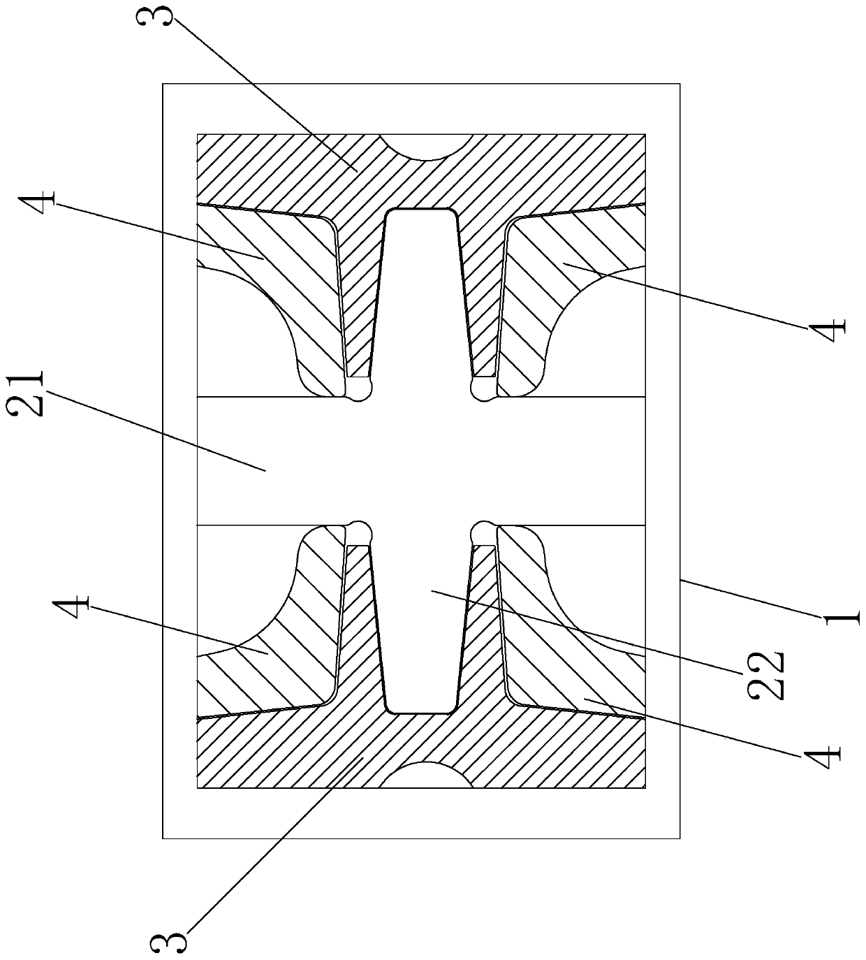
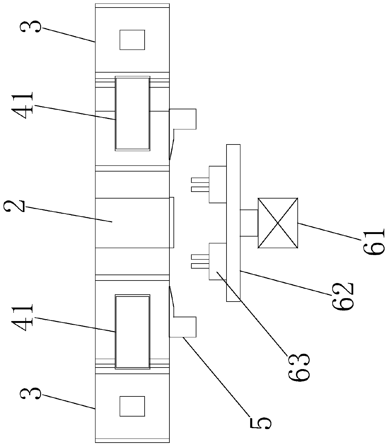
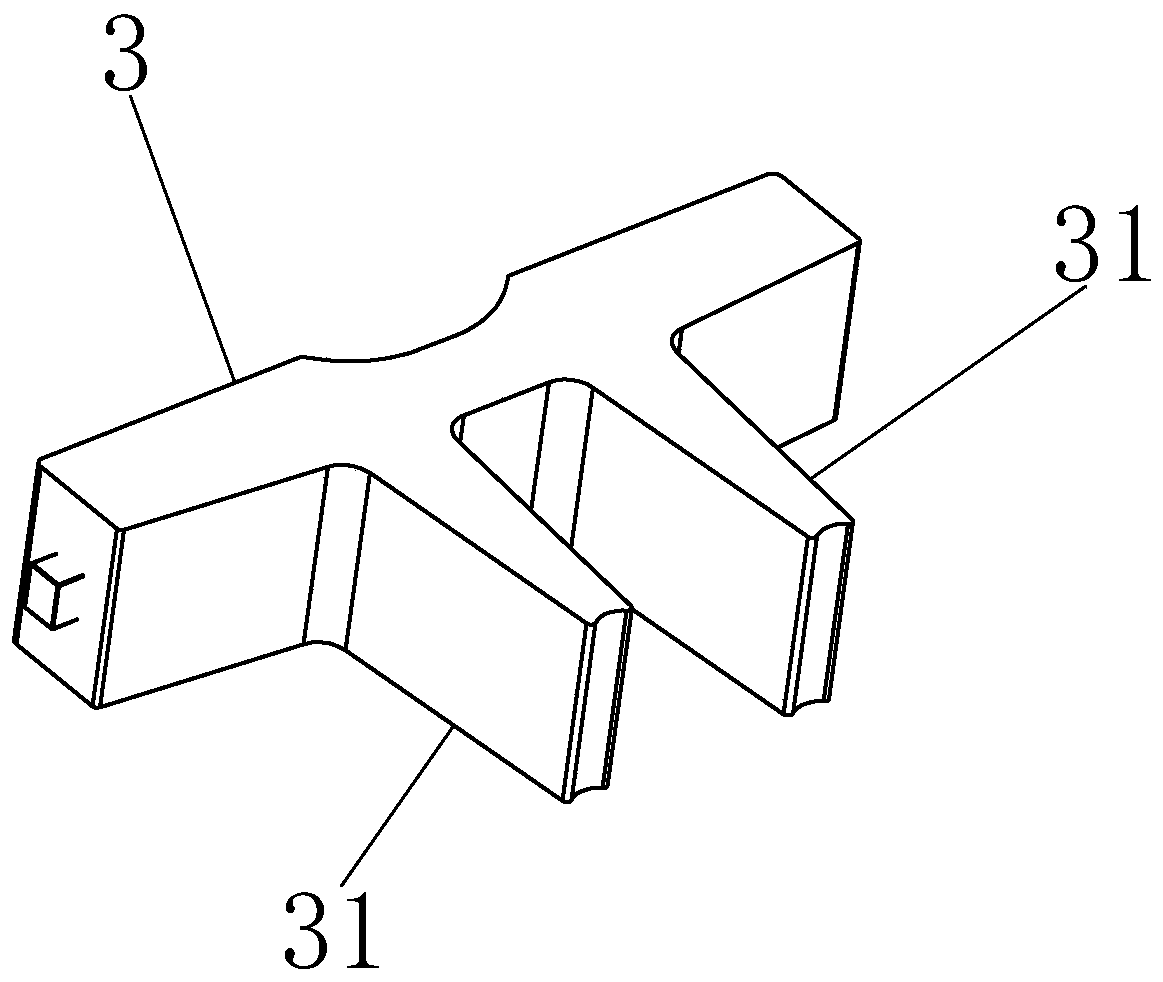
[0024] Such as figure 1 and figure 2 An inductor forming and cutting foot integrated machine is shown, which includes a bracket 1 with an inner hole, a cross-shaped base 2 fixed in the inner hole, and a first limiter that can be close to or away from the cross-shaped base 2 respectively. Block 3 and second limit block 4, the lower end of the cross-shaped base 2 is also provided with a cutting a...


PUM


Abstract

The invention relates to the technical field of inductor processing equipment, in particular to an inductor forming and foot shearing integrated machine. The machine comprises a bracket, a cross-shaped base, a first limiting block, a second limiting block, a clamping pull-down component and cutting component, wherein the bracket is provided with an inner hole, the cross-shaped base is fixedly arranged in the inner hole, the first limiting block and the second limiting block can approach or keep far away from the cross-shaped base, and the lower end of the cross-shaped base is further providedwith the clamping pull-down component and the cutting component. According to the inductor forming and foot shearing integrated machine, the inductor is placed on the cross-shaped base, and pins of the inductor are arranged in four quadrants of the cross-shaped base, the first limiting block and the second limiting block are linked to press pins to the corners of the vertical edge and the transverse edge of the cross-shaped base, thus the unified orientation of each pin is guaranteed; further more, the lower end of the pins is clamped by the clamping pull-down component, the pins are straightened, and finally the pins are cut to the uniform length through the cutting component. The inductor forming and foot shearing integrated machine has the advantages of being simple in operation and high in production efficiency, and is capable of ensuing the unified orientation and the length of the pins of the inductor, thus improving the product quality.

Description

technical field [0001] The invention relates to the technical field of inductor processing equipment, in particular to an inductor forming and cutting foot integrated machine. Background technique [0002] Inductors in the prior art include inductance coils and pins electrically connected to the inductance coils. The inductance needs to go through multiple processes during the processing process, and the lengths and orientation angles of the inductance pins are different, which makes subsequent processing inconvenient, thus greatly The production efficiency of inductance is reduced; For this reason, in the prior art, the pins of inductance are all cut off manually, so as to obtain uniform pin lengths, and the manual method is used to cut off the inductance pins, resulting in high labor intensity for operators, but It is difficult to ensure that the lengths of the pins are equal and the orientation is uniform, and the quality of the cut feet is difficult to guarantee. Conte...

Claims


Application Information

Patent Timeline
Patent Type & Authority Patents(China)
IPC IPC(8): B21F11/00B21F1/02
CPCB21F1/026B21F11/00
Inventor 杜勇
Owner ZHUHAI AINENG ELECTRONICS CO LTD
Learn More