Bogie traction device and application thereof

A technology of traction device and bogie, which is applied in the direction of relative movement between the bogie, the chassis and the bogie, transportation and packaging, and can solve the problem that the vehicle speed and the minimum curve radius cannot be met, and the bogie traction device Unable to adapt to the use environment and complex structure of electric drive subway rail engineering vehicles, to achieve the effect of meeting the requirements of vehicle speed and minimum curve radius, reliable transmission, and low traction point

Pending Publication Date: 2019-08-20
ZHUZHOU TIMES ELECTRONICS TECH CO LTD +1
View PDF1 Cites 14 Cited by
  • Summary
  • Abstract
  • Description
  • Claims
  • Application Information

AI Technical Summary

Problems solved by technology

[0007] In view of this, the purpose of the present invention is to provide a bogie traction device and its application to solve the problem that the existing bogie traction device cannot adapt to the use environment of electric drive subway rail engineering vehicles, and has a complex structure that cannot meet the vehicle speed and minimum curve Technical Issues with Radius Requirements

Method used


Image

  • Bogie traction device and application thereof
  • Bogie traction device and application thereof
  • Bogie traction device and application thereof

Examples


Embodiment 1

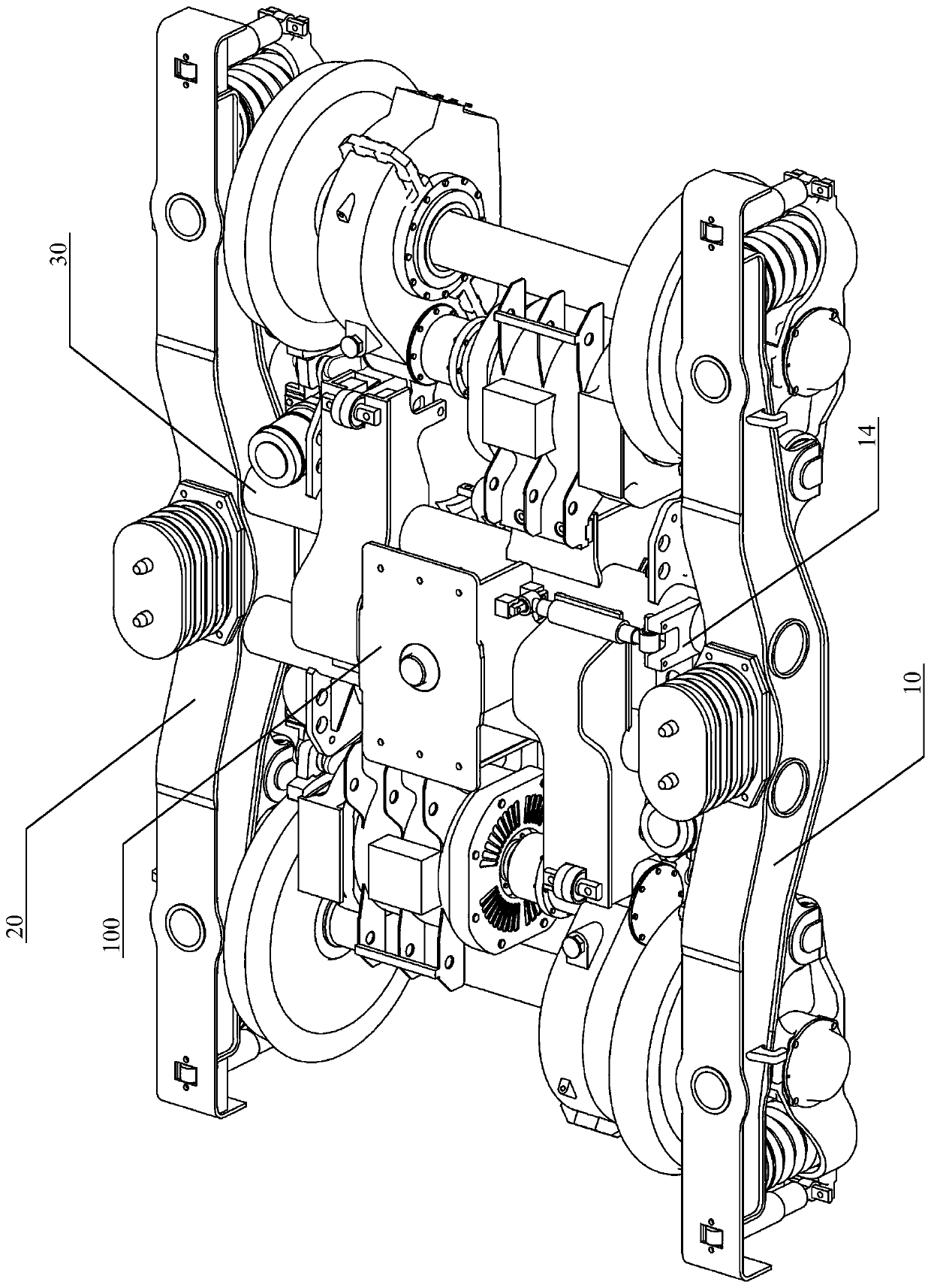
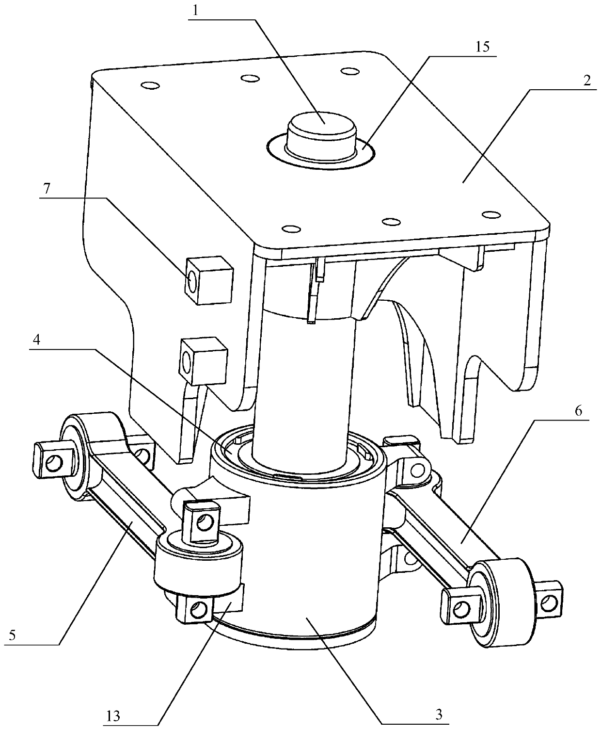
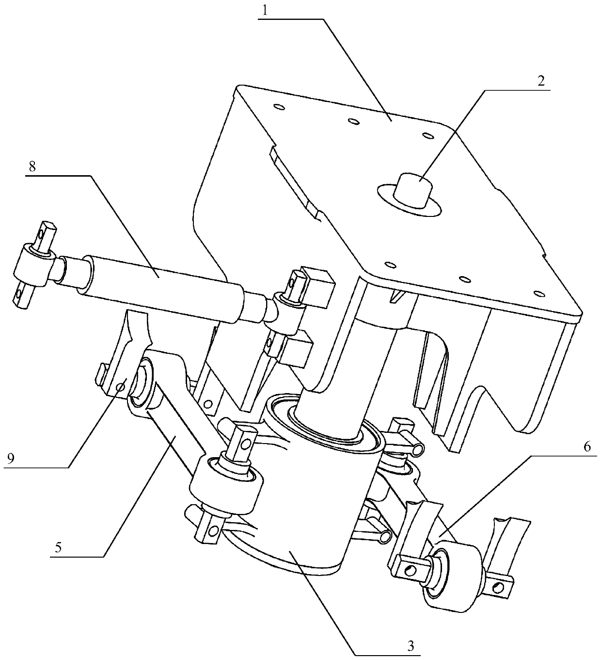
[0044] as attached figure 1 to attach image 3 As shown, an embodiment of the bogie traction device of the present invention, the bogie traction device 100 is installed on the bogie 10, and specifically includes: a center pin 1, a center pin seat 2, a center pin sleeve seat 3, and a first traction rod 5 and the second traction rod form 6.

[0045] The upper end of center pin 1 is press-fitted in the installation hole 15 of center pin seat 2 by interference fit, and the top of center pin seat 2 is connected with vehicle body.

[0046] The central pin sleeve 3 is sleeved on the lower end of the central pin 1 . The center pin sleeve 3 has a simple structure and adopts a sleeve shape, which is convenient for processing and replacement.

[0047] One end of the first traction link composition 5 and the second traction link composition 6 is connected to the side of the center pin sleeve 3, and the other end of the first traction link composition 5 and the second traction link comp...

Embodiment 2

[0057] as attached figure 1 Shown is an embodiment in which the bogie traction device described in Embodiment 1 is applied to an electric transmission rail vehicle, and the bogie 10 is specifically an electric transmission bogie. Further, the bogie 10 can be a bogie for an electric transmission subway track engineering vehicle, a light rail vehicle or a national railway main line vehicle.

[0058] The limit of subway engineering vehicles is slightly narrower than that of national railway engineering vehicles. In order to reliably transmit traction and braking forces and ensure stable operation and operation of vehicles, the bogie traction device 100 described in Embodiment 1 adopts a low-position traction point central pin traction structure, which can be applied It is used on electric transmission subway track engineering vehicles. Through dynamic calculation, the damping and various stiffness parameters of each spherical joint are designed, and the size of each component an...


PUM


Abstract

The invention discloses a bogie traction device and an application thereof. A traction device is mounted on a bogie and comprises a central pin, a central pin seat, a central pin sleeve seat and a first and second traction pull rod assembly. The upper end of the central pin is pressed in a mounting hole of the central pin seat through interference fit; the upper part of the central pin seat is connected with a vehicle body; and the central pin sleeve seat is arranged at the lower end of the central pin in a sleeving manner. One end of the first and second traction pull rod assembly is connected to the side part of the central pin sleeve seat; and the other end of the first and second traction pull rod assembly is connected to a cross beam of a bogie framework. The central pin sleeve seat is connected with the bogie framework through the first and second traction pull rod assembly; and the first and second traction pull rod assembly is used for stably transmitting a traction force and abraking force. According to the bogie traction device, technical problems that an existing bogie traction device cannot adapt to an electric transmission subway track engineering vehicle use environment, the structure of the existing bogie traction device is complicated, and the existing bogie traction device cannot satisfy requirements of vehicle speed and minimum curve radius can be solved.

Description

technical field [0001] The invention relates to the technical field of rail engineering vehicles, in particular to a bogie traction device of an electric transmission subway engineering vehicle and an application thereof. Background technique [0002] Most of the running parts of modern vehicles are in the form of bogies. The main functions are: 1. Bear the weight of the parts above the frame; 2. Ensure the necessary adhesion; 3. Make the vehicle have good stability and stability during operation; 4. Ensure that the vehicle passes the curve smoothly; 5. Generate the necessary braking force. Among them, the traction device, as a key component connecting the bogie and the car body, has the following main functions: 1. To adapt to the rotation of the bogie relative to the car body; 2. To transmit tractive force and braking force. When the vehicle is running normally, the force transmitted by the tow bar is usually small, and the deformation of the elastic node is also small. ...

Claims


Application Information

Patent Timeline
Patent Type & Authority Applications(China)
IPC IPC(8): B61F5/24B61F5/50
CPCB61F5/24B61F5/245B61F5/50
Inventor 姜子良肖少坤王建宏李永江周浩
Owner ZHUZHOU TIMES ELECTRONICS TECH CO LTD
Why Eureka
Try Eureka