Novel electric hair drier

A hair dryer, a new type of technology, applied in the field of hair dryer, can solve the problems of inconvenient storage or portability, large space occupation, etc., and achieve the effect of easy storage or portability and small space occupation

Pending Publication Date: 2019-08-23
JIAXING ZIGE ELECTRIC TECH CO LTD
View PDF0 Cites 2 Cited by
  • Summary
  • Abstract
  • Description
  • Claims
  • Application Information

AI Technical Summary

Problems solved by technology

[0002] The structures of the existing hair dryers are all T-shaped or L-shaped structures, which occ

Method used


Image

  • Novel electric hair drier
  • Novel electric hair drier
  • Novel electric hair drier

Examples


Embodiment Construction

[0028] Specific embodiments of the present invention will be described in further detail below based on the accompanying drawings. It should be understood that the description of the embodiments of the present invention here is not intended to limit the protection scope of the present invention.

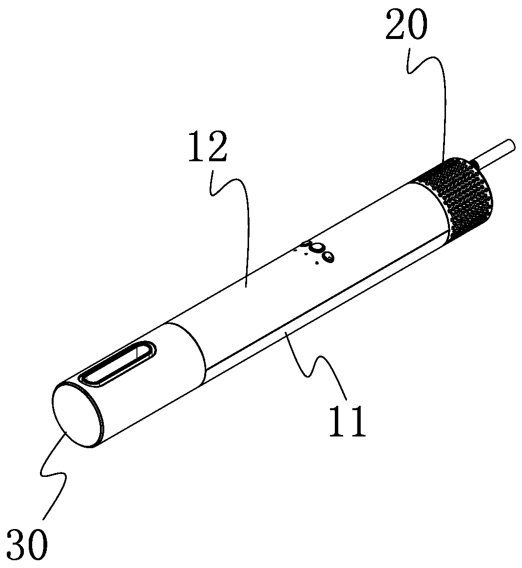
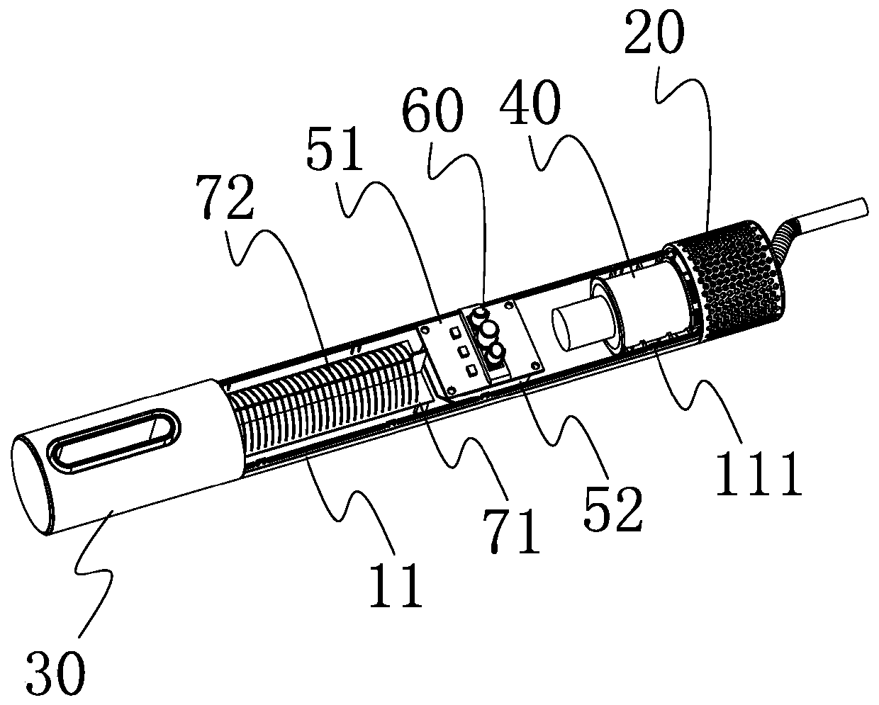
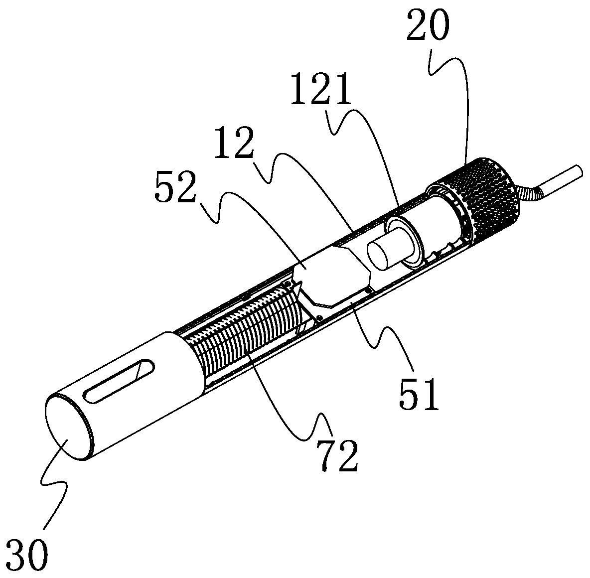
[0029] Please refer to Figure 1 to Figure 3 The novel hair dryer provided by the present invention comprises a cylindrical housing, a cylindrical air inlet unit 20 arranged at the first end of the housing, a cylindrical air nozzle unit 30 arranged at the second end of the housing, and a Fan 40, control circuit board, heating wire support frame 71, heating wire 72 in the housing.

[0030] The housing includes a base 11 and an upper cover 12 that are snap-connected relative to each other.

[0031] The blower 40 is arranged at one end of the casing close to the air inlet unit 20 , the heating wire support frame 71 is arranged at one end of the casing close to the tuyere unit 30 , and...


PUM


Abstract

The invention discloses a novel electric hair drier, including a cylindrical shell body, a cylindrical air inlet unit arranged at a first end of the shell body, a cylindrical air grille unit arrangedat a second end of the shell body, and a fan, a control circuit board, a heating wire supporting frame and a heating wire which are arranged in the shell body; the fan is arranged at the end, near theair inlet unit, of the shell body, the heating wire supporting frame is arranged at the end, near the air grille unit, of the shell body, the heating wire is arranged on the heating wire supporting frame in a spiral shape, and the control circuit board is arranged between the fan and the heating wire supporting frame. According to the novel electric hair drier, a whole body of the novel electrichair drier is cylindrical to occupy small space, and convenient to store or carry.

Description

technical field [0001] The invention relates to the technical field of hair dryers, in particular to a novel hair dryer. Background technique [0002] The structures of the existing hair dryers are all T-shaped or L-shaped structures, which occupy a large space when placed in containers such as suitcases, and are inconvenient to store or carry. Contents of the invention [0003] In view of this, the present invention provides a new type of hair dryer which is cylindrical as a whole, takes up little space, and is easy to store or carry, so as to solve the above problems. [0004] A new type of hair dryer, comprising a cylindrical housing, a cylindrical air inlet unit disposed at the first end of the housing, a cylindrical air nozzle unit disposed at the second end of the housing, and a Fan, control circuit board, heating wire support frame, heating wire; the fan is set at one end of the housing close to the air inlet unit, the heating wire support frame is set at the end o...

Claims


Application Information

Patent Timeline
IPC IPC(8): A45D20/10A45D20/12
CPCA45D20/10A45D20/12A45D2020/126A45D2020/128
Inventor 陈添
Owner JIAXING ZIGE ELECTRIC TECH CO LTD
Why Eureka
Try Eureka