Differential bearing mounting device with bilateral bearing self-centering function and mounting method thereof

A technology of installation device and differential gear, which is applied in the direction of assembly machine, metal processing, metal processing equipment, etc., can solve the problems of difficulty in ensuring assembly accuracy, low efficiency and low efficiency of the screw pair driving clamping mechanism, and achieves good centering. , to avoid effects that are individually controlled and driven

CN110153687AInactive Publication Date: 2019-08-23ANYANG INST OF TECH
10 Cites 9 Cited by

Patent Information

Authority / Receiving Office
CN · China
Patent Type
Applications(China)
Current Assignee / Owner
Publication Date
2019-08-23
Estimated Expiration
Not applicable · inactive patent

Smart Images

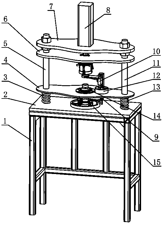
  • Figure 1
    Figure 1
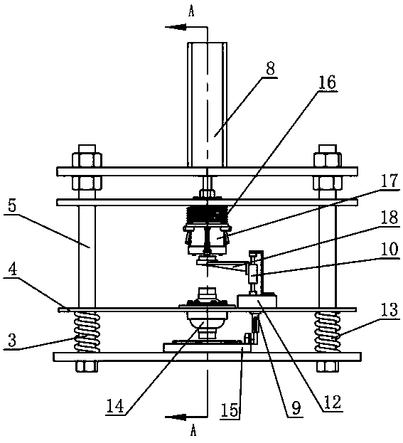
  • Figure 2
    Figure 2
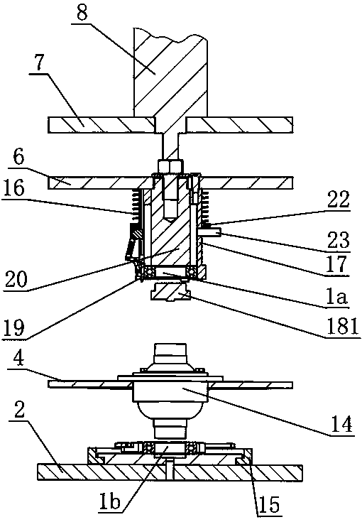
  • Figure 3
    Figure 3
Patent Text Reader

Abstract

The invention discloses a differential bearing mounting device with a bilateral bearing self-centering function. The differential bearing mounting device comprises upper-side self-centering bearing clamping mechanisms, lower-side self-centering bearing clamping mechanisms and a bottom plate; the lower ends of a left upright column and a right upright column are fixed to the bottom plate; a differential carrier plate and a pressure plate are in sliding connection with the left upright column and the right upright column; the cylinder fixing plate is fixed to the left upright column and the right upright column; a lifting cylinder is fixed to the cylinder fixing plate; a mandrel and the pressure plate are fixed with a piston rod of the lifting cylinder; a bearing fixing seat is fixed to thepressure plate; the bearing fixing seat and the mandrel are provided with a cylindrical cavity for accommodating an upper-side bearing; the upper-side self-centering bearing clamping mechanisms are arranged on the bearing fixing seat; the lower-side self-centering bearing clamping mechanisms are arranged on the bottom plate; the differential carrier plate is provided with a structure for fixing adifferential and an upper-side bearing lifting mechanism; the left upright column is provided with a left compression spring between the differential carrier plate and the bottom plate; and the rightupright column is provided with a right compression spring between the differential carrier plate and the bottom plate. The self-centering fixing of the upper-side bearing and a lower-side bearing ofthe differential is realized, and the mounting of the bilateral bearings of the differential is simpler and more convenient.
Need to check novelty before this filing date? Find Prior Art

Description

technical field

[0001] The invention relates to a differential gear bearing installation device and an installation method with double-side bearing self-centering, and belongs to the technical field of differential gear tooling. Background technique

[0002] The protruding cylinders at both ends of the vehicle differential require bearing rotation support. In order to improve the reliability of the differential support and the rotation accuracy during operation, the inner holes of the bearings at both ends and the outer cylindrical surface of the differential adopt an interference fit. Smaller enterprises usually use manual assembly, which is inefficient and difficult to ensure assembly accuracy. Before the bearing is installed at the end of the differential, it needs to be fixed in advance. The efficiency of the screw drive clamping mechanism is low, and the magnetic suction is adopted The method is easy to attract the bearing to the deflection, and the bearing is pressed i...

Examples

Embodiment Construction

[0060] combine Figure 1-13 , a double-sided bearing self-centering differential bearing installation device of the present invention, including a base frame 1, a bottom plate 2, a left compression spring 3, a differential support plate 4, a left column 5, a pressure plate 6, and a cylinder Fixed plate 7, lifting cylinder 8, lower pressure seat 9, slide table cylinder 10, right column 11, electric turntable 12, right compression spring 13, rotating disc 15, clamping spring 16, bearing fixing seat 17, bearing bracket 18, Clamping block 19, mandrel 20, synchronous ring 22, stop pin 23, connecting rod 1 24, connecting rod 2 25, slider 26, hinge shaft 27, guide block 28, driving rod 29, fixed disc 30, pressing block 31, column pin one 32, column pin two 33, column pin three 34, press down bar 35, press down spring 36, control system, with attached figure 2 The orientation defines the up-down and left-right directions of the application, and the direction in which the inner diame...