Twist drill for machining holes of laminated welded steel

A hole processing and twist drilling technology, which is applied in twist drills, metal processing equipment, drilling/drilling equipment, etc., can solve the problem of the sharpness of the peripheral cutting edge, the deviation of the drill bit and the opening of the hole, which affect the self-centering ability of the drill tip. The burr is too large, which affects the service life of the drill bit, etc., so as to reduce the occurrence rate of the burr in the hole, make it easy to drill into the workpiece, and reduce the effect of unstable centering

Active Publication Date: 2020-02-28
ZHUZHOU CEMENTED CARBIDE CUTTING TOOLS CO LTD
View PDF11 Cites 3 Cited by
  • Summary
  • Abstract
  • Description
  • Claims
  • Application Information

AI Technical Summary

Problems solved by technology

[0003] In the prior art, twist drills for drilling steel parts can generally adopt negative chamfering or grinding process to strengthen the cutting edge to increase the service life of twist drills, but the currently known edge strengthening of steel drills is along the The positions of the rake face and the flank face of the cutting edge are treated (chamfered or ground) on the top of the main cutting edge of the entire drill point. Although this treatment can strengthen the cutting edge and prolong the service life of the drill bit, it will also cause the drill point to be horizontal. The sharpness of the cutting edge at the end point of the edge and the outer periphery is reduced, so the self-centering ability of the drill tip and the sharpness of the outer peripheral cutting edge are greatly affected, resulting in easy drilling deviation and holes when drilling double-layer welded steel. The burrs in the mouth are too large, which affects the service life of this type of drill

Method used


Image

  • Twist drill for machining holes of laminated welded steel
  • Twist drill for machining holes of laminated welded steel
  • Twist drill for machining holes of laminated welded steel

Examples


Embodiment 1

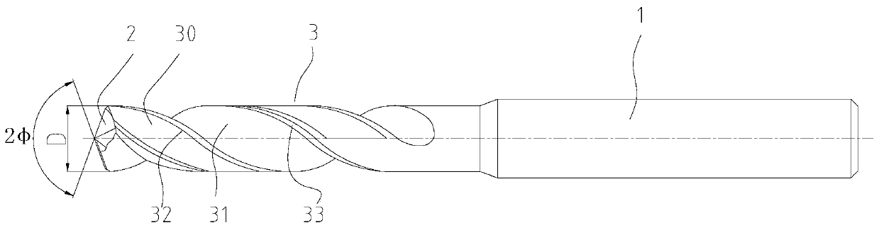
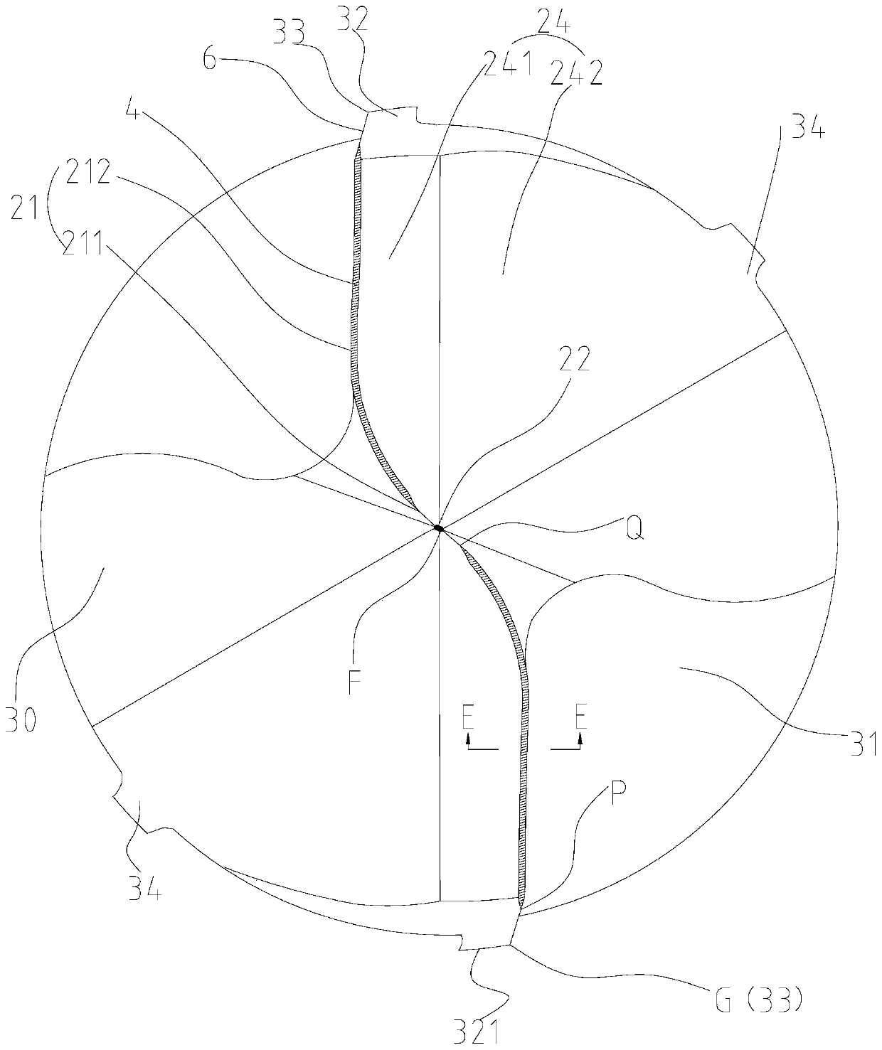
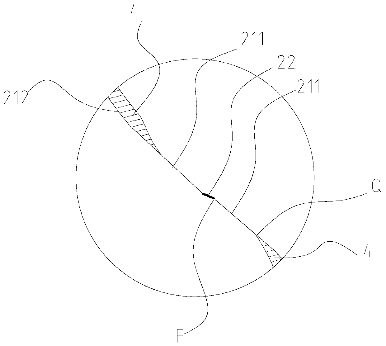
[0032] Such as Figure 1 to Figure 6 As shown, the twist drill used for hole processing of laminated welded steel in this embodiment includes a cutting part and a shank 1, the cutting part includes a drill point 2 and a secondary cutting part 3, and the drill point 2 is provided with two main cutting edges 21 and the chisel edge 22 connecting the two main cutting edges 21, the secondary cutting part 3 is provided with two flutes 31 and two first lands 32, the first lands 32 intersect with the flutes 31 to form a secondary cutting The edge 33 and the secondary cutting portion 3 are composed of two blades 30 , the first land 32 is provided on the blade 30 , and the first land 32 is provided with a peripheral edge 321 , the peripheral edge 321 intersects with the secondary cutting edge 33 . The main cutting edge 21 is provided with a negative chamfer 4, and the negative chamfer 4 does not pass through the intersection of the main cutting edge 21 and the chisel edge 22. The length...

Embodiment 2

[0043] Such as Figure 7 As shown, the twist drill used for hole processing of stacked welded steel products in this embodiment is basically the same as that in Embodiment 1, the only difference is that:

[0044] In this embodiment, the negative chamfer 4 on the main cutting edge 21 is replaced by a honing surface 5, and the honing surface 5 is an outwardly convex arc surface. The honing surface 5 can also strengthen the drill tip, and the value of the rake angle γ1 of the honing surface 5 is the angle between the line connecting the two starting points of the arc and the axis.

[0045] The rest are the same as in Embodiment 1, and will not be repeated here.


PUM


Abstract

The invention discloses a twist drill for machining holes of laminated welded steel. The twist drill for machining holes of the laminated welded steel includes a cutting part and a shank part. The cutting part includes a drill tip and a secondary cutting part, and the drill tip is provided with two main cutting edges and a chisel edge connecting the two main cutting edges. The secondary cutting part is provided with two chip discharging grooves and two first cutting edge belts, and the first cutting edge belts and the chip discharging grooves intersect to form a secondary cutting edge. The main cutting edges are provided with negative chamfers, and the negative chamfers do not pass the intersections of the main cutting edges and the chisel edge. The length of the chisel edge is L5, whereinthe L5 is larger than or equal to 0.017D and less than or equal to 0.03D, and D is the diameter of the cutting part. According to the twist drill for hole machining of the laminated welded steel, thelength of the chisel edge is only one third of that of a conventional chisel edge, the length of the chisel edge of the drill tip is small, the centering capacity during drilling of the laminated welded steel is increased, the twist drill for hole machining of the laminated welded steel is suitable for drilling machining of steel with varying hardness among different materials, the problem of drilling deviation in the drilling process is reduced, the negative chamfers are arranged on the main cutting edge, no negative chamfer is arranged on the entire chisel edge, and the sharpness of the chisel edge is not changed while the strength of the main cutting edge is increased, so that the centering performance of the chisel edge is better.

Description

technical field [0001] The invention relates to a metal cutting tool, in particular to a twist drill for hole processing of laminated welded steel materials. Background technique [0002] In the field of mechanical processing, in order to ensure the safety of automobiles, it is necessary to process connection holes on automobile load-bearing parts (such as shock absorber seats, automobile chassis brackets, etc., which adopt double-layer welded steel support technology), because these connection holes affect the safety of automobiles. Safety performance, so there are requirements for its accuracy and the size of the hole exit burr. [0003] In the prior art, twist drills for drilling steel parts can generally adopt negative chamfering or grinding process to strengthen the cutting edge to increase the service life of twist drills, but the currently known edge strengthening of steel drills is along the The positions of the rake face and the flank face of the cutting edge are t...

Claims


Application Information

Patent Timeline
Patent Type & Authority Applications(China)
IPC IPC(8): B23B51/02B23B51/08
CPCB23B51/02B23B51/08
Inventor 肖跃勇王强方曙璋罗胜
Owner ZHUZHOU CEMENTED CARBIDE CUTTING TOOLS CO LTD
Why Eureka
Try Eureka