Die cutting machine having good use effect and being convenient to adjust

A die-cutting machine and block cutting technology, which is applied in metal processing, winding strips, thin material processing, etc., can solve the problems of poor die-cutting effect and low die-cutting efficiency, and achieve reduced production costs and good die-cutting effect , the effect of saving electric energy

Active Publication Date: 2019-08-23
苏州东琨科技有限公司
View PDF7 Cites 1 Cited by
  • Summary
  • Abstract
  • Description
  • Claims
  • Application Information

AI Technical Summary

Problems solved by technology

[0007] Aiming at the deficiencies of the prior art, the present invention provides a die-cutting machine with good use effect and easy adjustment, which can simultaneously carry out die-cutting of two material rolls to improve die-cutting efficiency and facilitate adjustment and control of die-cutting depth to improve die-cutting Effect and other advantages, to solve the problem of low die-cutting efficiency and poor die-cutting effect

Method used


Image

  • Die cutting machine having good use effect and being convenient to adjust
  • Die cutting machine having good use effect and being convenient to adjust
  • Die cutting machine having good use effect and being convenient to adjust

Examples


Embodiment Construction

[0026] The following will clearly and completely describe the technical solutions in the embodiments of the present invention with reference to the accompanying drawings in the embodiments of the present invention. Obviously, the described embodiments are only some, not all, embodiments of the present invention. Based on the embodiments of the present invention, all other embodiments obtained by persons of ordinary skill in the art without making creative efforts belong to the protection scope of the present invention.

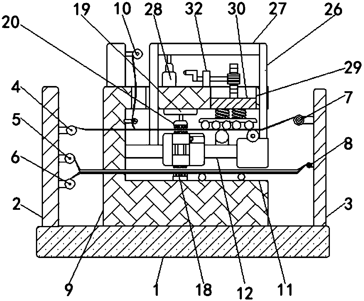
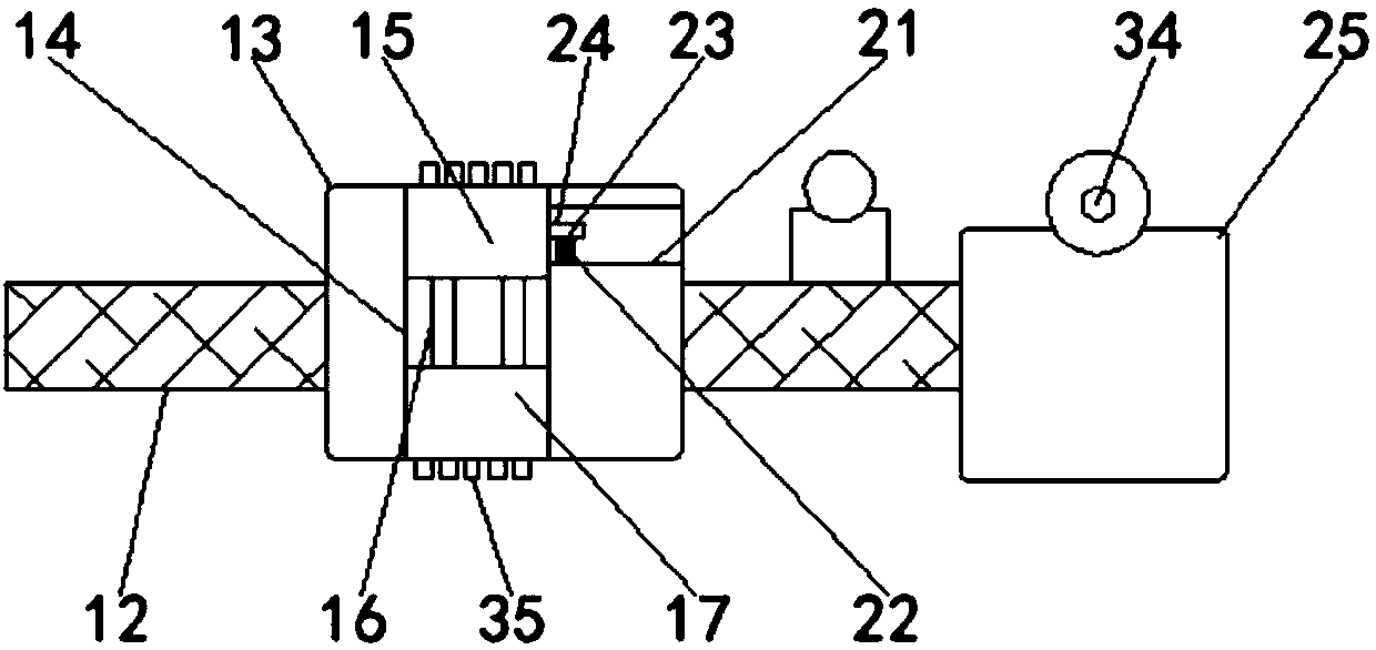
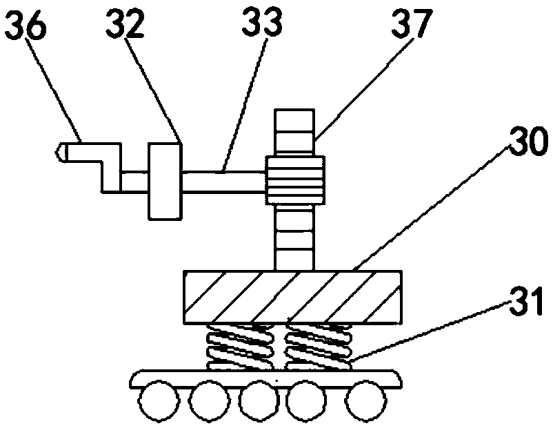
[0027] see Figure 1-3, the present invention provides a technical solution: a die-cutting machine with good use effect and easy adjustment, including a base 1, the top of the base 1 is fixedly installed with a first column 2 and a second column 3 in turn from left to right, the first The right side of the column 2 is fixedly installed with the first receiving roller 4, the second receiving roller 5 and the second traction roller 6 successively from top to bot...


PUM


Abstract

The invention relates to the technical field of machining, and discloses a die cutting machine having a good use effect and being convenient to adjust. The die cutting machine comprises a base, wherein a first upright post and a second upright post are sequentially and fixedly mounted on the top of the base from left to right; and a first material receiving roller, a second material receiving roller and a second traction roller are sequentially and fixedly mounted on the right side of the first upright post from top to bottom. According to the die cutting machine having the good use effect andbeing convenient to adjust disclosed by the invention, through cooperation among the base, the first upright post, the second upright post, the first material receiving roller, the second material receiving roller, a first feeding roller, a second feeding roller, a foundation base, a groove, a cross plate, a first supporting block, a first through hole, an upper cutting block, a connecting rod, alower cutting block, a lower die cutting table, an electric push rod, an upper die cutting table, a passing hole, a spring, a limiting plate, a limiting rib, a second supporting block and a roller wheel, the upper die cutting table and the lower die cutting table can simultaneously do die cutting operations, and only in need of one electric push rod, the die cutting efficiency is improved, and electric energy is also economized.

Description

technical field [0001] The invention relates to the technical field of mechanical processing, in particular to a die-cutting machine with good use effect and easy adjustment. Background technique [0002] Machining refers to the process of changing the shape or performance of a workpiece through a mechanical device. According to the difference in processing methods, it can be divided into cutting processing and pressure processing. [0003] Die cutting machine is a kind of mechanical processing equipment widely used in packaging and other industries. Die cutting machine is also called beer machine, cutting machine and CNC punching machine. It is mainly used for some corresponding non-metallic materials, self-adhesive, EVA, Die-cutting, full-cutting, half-cutting, indentation and bronzing operations of surface glue, electronic and mobile phone rubber pads, etc. Die-cutting machines use steel knives, metal molds and steel plates to engrave templates, and apply certain pressure...

Claims


Application Information

Patent Timeline
Patent Type & Authority Applications(China)
IPC IPC(8): B26F1/38B26D7/32B26D7/26B26D5/08B26D7/08B65H18/10
CPCB26D5/08B26D7/08B26D7/2628B26D7/32B26D2007/322B26F1/38B65H18/103
Inventor 刘会
Owner 苏州东琨科技有限公司
Why Eureka
Try Eureka