Supercharge Your Innovation With Domain-Expert AI Agents!

Vehicle control method, and control device for vehicle system and vehicle

A control method and braking device technology, which are applied in the field of vehicle control devices, can solve the problems that the turning performance of the vehicle cannot be fully improved, and achieve the effect of improving the turning performance of the vehicle

Active Publication Date: 2019-08-23
MAZDA MOTOR CORP
View PDF10 Cites 2 Cited by
  • Summary
  • Abstract
  • Description
  • Claims
  • Application Information

AI Technical Summary

Problems solved by technology

Therefore, when the vehicle is decelerating, the suspension spring on the front side of the vehicle is in a compressed state, so if the vehicle posture control is performed in this state, the sinking of the vehicle front side when the deceleration is added by this control is insufficient. , sometimes cannot fully improve vehicle cornering performance

Method used


Image

  • Vehicle control method, and control device for vehicle system and vehicle
  • Vehicle control method, and control device for vehicle system and vehicle
  • Vehicle control method, and control device for vehicle system and vehicle

Examples


no. 1 Embodiment approach >

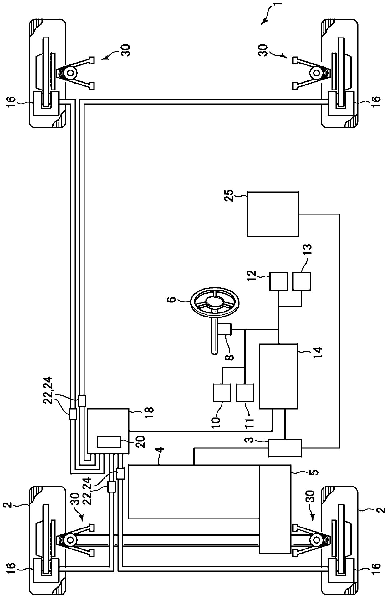
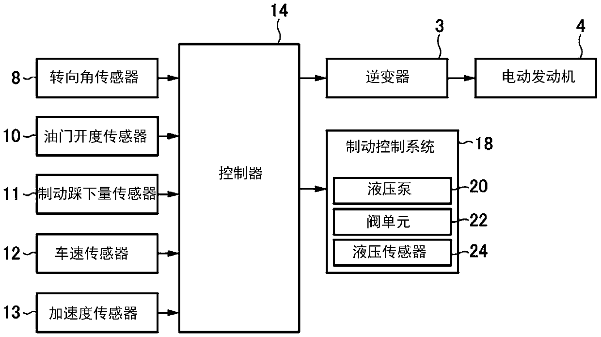
[0040] First, the first embodiment of the present invention will be described. First, based on figure 1 A system configuration of a vehicle equipped with the vehicle control device according to the first embodiment of the present invention will be described. figure 1 It is a block diagram showing the overall configuration of a vehicle equipped with the vehicle control device according to the first embodiment of the present invention.

[0041] exist figure 1 In , reference numeral 1 denotes a vehicle on which the vehicle control device according to the present embodiment is mounted. The motor generator 4 is mounted on the vehicle 1, and the motor generator 4 has a function of driving the front wheels 2 (in other words, a function as an electric motor) and a function of regenerative power generation driven by the front wheels 2 (in other words, as a power generator). function of the machine). The motor generator 4 transmits power to and from the front wheels 2 via a reductio...

no. 2 Embodiment approach >

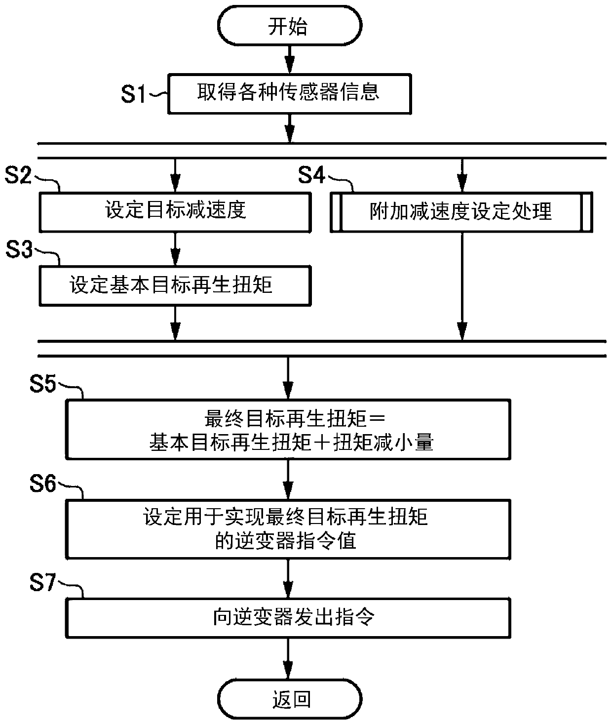
[0083]Next, a second embodiment of the present invention will be described. In the above-mentioned first embodiment, the present invention is applied to the vehicle 1 (EV vehicle) driven by the motor generator 4. In the second embodiment, the present invention is applied to a normal vehicle driven by the engine. in the vehicle. Furthermore, in the first embodiment, during the vehicle attitude control, the motor generator 4 is caused to perform regenerative power generation to generate additional deceleration in the vehicle 1 (see image 3 ), however, in the second embodiment, the additional deceleration of the vehicle is generated by applying the braking force by the braking device 16 during the vehicle attitude control.

[0084] Note that, below, descriptions of the same configurations (including control and processing) as those of the first embodiment will be appropriately omitted. In other words, configurations not particularly described here are the same as those in the ...


PUM


Abstract

In a vehicle control method for vehicle attitude control for applying a deceleration to the vehicle when a steering device is subjected to steering operation, improvement effects of vehicle steering performance under control during deceleration can be properly ensured. The method includes a step for determining on the basis of a steering angle detected by a steering angle sensor (8), whether a steering device including a steering wheel (6) and the like has been turned or not; a step for applying deceleration to a vehicle (1) by causing a motor generator (4) to perform regeneration so as to control vehicle attitude when it is determined that the steering device has been turned; and a step for applying a greater amount of deceleration, applied to the vehicle (1) to control the vehicle attitude, when the deceleration generated in the vehicle (1) is a first value than when the deceleration generated in the vehicle (1) is a second value smaller than the first value.

Description

technical field [0001] The present invention relates to a vehicle control method, a vehicle system, and a vehicle control device for controlling vehicle posture. Background technique [0002] Conventionally, when the behavior of the vehicle becomes unstable due to slipping or the like, techniques (such as a side-slip prevention device) for controlling the behavior of the vehicle in a safe direction are known. Specifically, when the vehicle is turning, etc., whether the vehicle is understeering or oversteering is detected, and an appropriate deceleration is applied to the wheels to suppress the understeering or oversteering. [0003] On the other hand, there is known a vehicle motion control device that adjusts the deceleration at the time of steering so that the vehicle in the normal running state is at The series of operations performed by the driver (braking, wheeling, acceleration, and turning back, etc.) by the driver are natural and stable when turning. [0004] Furth...

Claims


Application Information

Patent Timeline
IPC IPC(8): B60L15/20B60L7/10B60L7/24B60W30/045B60W10/04B60W10/188
CPCB60L15/2009B60L7/10B60L7/24B60W30/045B60W10/04B60W10/188B60L2240/12B60L2240/14B60L2240/24B60W2520/10B60W2540/10B60W2540/12B60W2540/18B60W2720/106B60L15/20B60W10/08B60L7/14Y02T10/72B60L7/18Y02T10/64B60W2520/105B60W2710/083B60W2510/205B60W30/18127B60W10/184B60W2710/182B60W2540/165
Inventor 梅津大辅砂原修小川大策
Owner MAZDA MOTOR CORP
Features
  • R&D
  • Intellectual Property
  • Life Sciences
  • Materials
  • Tech Scout
  • Unparalleled Data Quality
  • Higher Quality Content
  • 60% Fewer Hallucinations
Learn More