
Power control method and device

A technology of power control, power value, applied in the field of information

Active Publication Date: 2019-08-23
HUAWEI TECH CO LTD
View PDF1 Cites 8 Cited by
  • Summary
  • Abstract
  • Description
  • Claims
  • Application Information

AI Technical Summary

Problems solved by technology

[0005] In view of this, the present application provides a power control method and device to provide a power control method to solve the problem of effective power control of dual-connection communication devices under different standards

Method used


Image

  • Power control method and device
  • Power control method and device
  • Power control method and device

Examples


Embodiment Construction

[0056] The application will be described in further detail below in conjunction with the accompanying drawings.

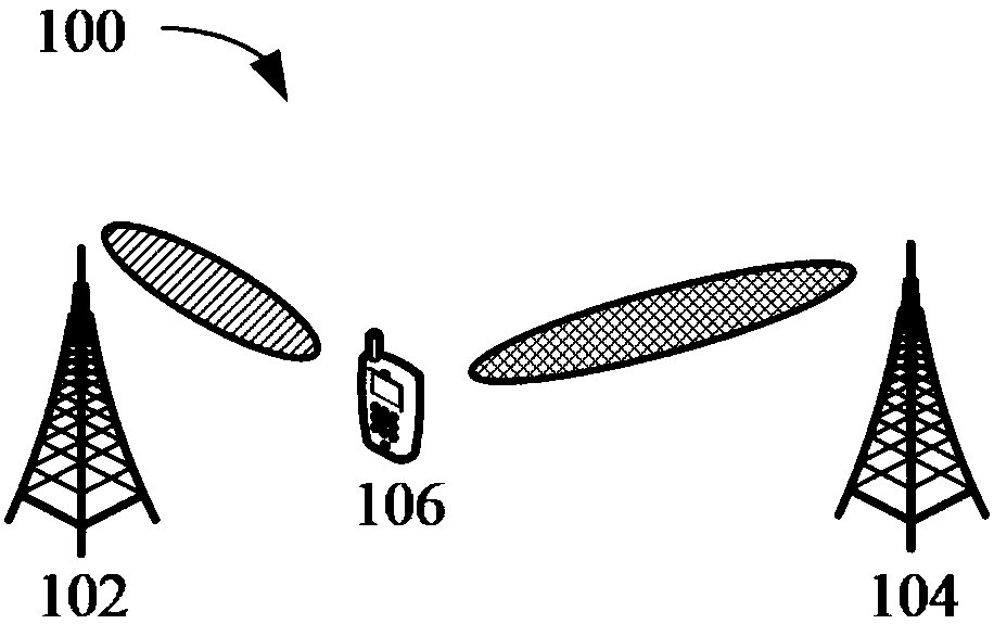
[0057] In order to facilitate the understanding of the embodiment of the present application, first use figure 1 The communication system shown in is used as an example to describe in detail the communication system applicable to the embodiment of the present application. figure 1 A schematic diagram of a communication system applicable to the communication method of the embodiment of the present application is shown. Such as figure 1 As shown, the communication system 100 includes a network device 102 and a communication device 106. The network device 102 may be configured with multiple antennas, and the terminal device may also be configured with multiple antennas. Optionally, the communication system may further include a network device 104, and the network device 104 may also be configured with multiple antennas.

[0058] It should be understood that the net...


PUM


Abstract

The invention discloses a power control method and device. The device comprises: a device; the communication device firstly receives a first power value and a second power value configured at a network side; wherein the first power value is the maximum allowable transmission power value of the first cell group configured for the communication equipment device by the network side; wherein the second power value is the maximum allowable sending power value of a second cell group configured by the network side for the communication equipment; therefore, the communication equipment device determines the total guaranteed power value of the communication equipment when the resources of the first cell group and the second cell group are overlapped according to the first power value and the secondpower value, so that the problem of effective power control of the dual-connection communication equipment device under different standards can be solved.

Description

technical field [0001] The present application relates to the field of information technology, and in particular to a power control method and device. Background technique [0002] Version 12 (Release 12) of the standard protocol introduces a dual connectivity (dual connectivity, DC) technology. Wherein, the DC technology means that the terminal device can connect to two cell groups at the same time. For example, the first cell group may be long term evolution (long term evolution, LTE) cells, and the second cell group may be new radio (new radio, NR) cells. [0003] At the same time, the standard protocol also stipulates that when the terminal equipment is in the DC state, it can send uplink signals to the primary base station and the secondary base station at the same time, and the power of the uplink signal sent to the primary base station is the sum of the power of the uplink signal sent to the secondary base station. The preset maximum power must not be exceeded. For...

Claims


Application Information

Patent Timeline
IPC IPC(8): H04W52/14H04W52/34
CPCH04W52/14H04W52/34H04W76/15H04W52/40H04W76/16H04W52/367H04W52/146H04W52/42
Inventor 张茜张兴炜刘哲冯淑兰邓猛
Owner HUAWEI TECH CO LTD
Learn More