
Liquid absorbing floating ball device for oil-water separation

An oil-water separation and liquid flotation technology, applied in liquid separation, separation methods, chemical instruments and methods, etc., can solve problems such as difficulty, air suction, limited efficiency, etc., achieve simple production and processing, continuous separation process, and speed up the reaction. effect of speed

Pending Publication Date: 2019-08-27
SHANGHAI GREENSUN ENVIRONMENTAL PROTECTION TECH CO LTD
View PDF0 Cites 1 Cited by
  • Summary
  • Abstract
  • Description
  • Claims
  • Application Information

AI Technical Summary

Problems solved by technology

Considering that the existing oil-water separator is generally composed of an oil-absorbing floating device, a pneumatic pump, and an oil-water separation treatment room, etc., its filter suction port is small and prone to clogging, so it cannot efficiently solve the problem of the separated oil during the liquid surface floating process. The problem of containing a large amount of oil-water mixture in
Another floating ball is complicated and difficult to manufacture, and it will also cause air or impurities to be mixed into the oil suction port. The pump used is a pneumatic pump with a small flow rate, which is likely to cause air suction. Large-scale oil-water separation needs
[0004] At present, the common oil-water separator is prone to discontinuous suction process, and the oil-water separation effect is poor. The oil suction port is often not at the oil-water separation interface all the time, resulting in water mixing, which is not conducive to the subsequent fine separation of oil and water.

Method used


Image

  • Liquid absorbing floating ball device for oil-water separation
  • Liquid absorbing floating ball device for oil-water separation
  • Liquid absorbing floating ball device for oil-water separation

Examples


Embodiment Construction

[0035] The technical solutions of the present invention will be further described below with reference to the accompanying drawings and embodiments.

[0036] In the present invention, "upper" and "lower" refer to the orientation of components in the use state of the device.

[0037] The device of the present invention includes two parts of floating ball oil-water separation and electric suction.

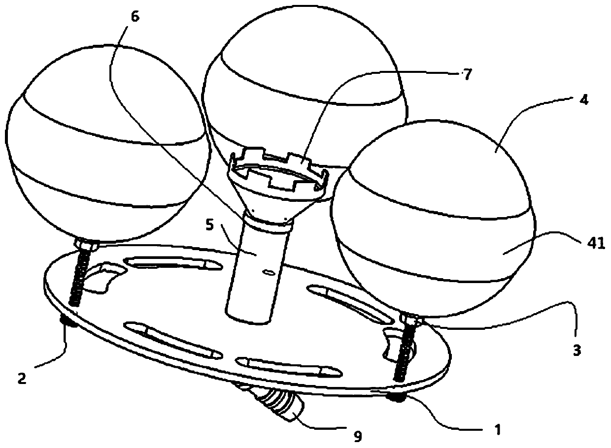
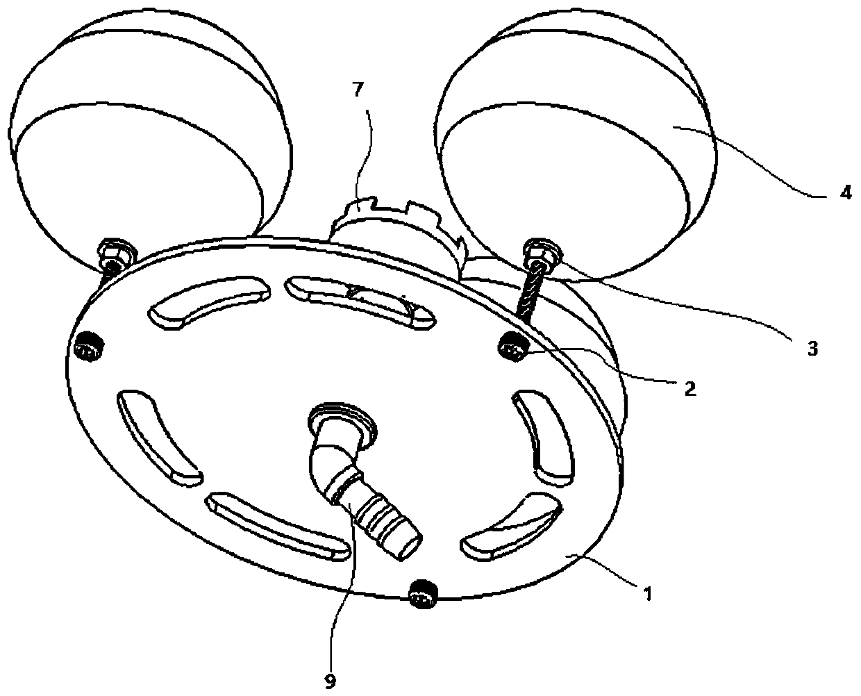
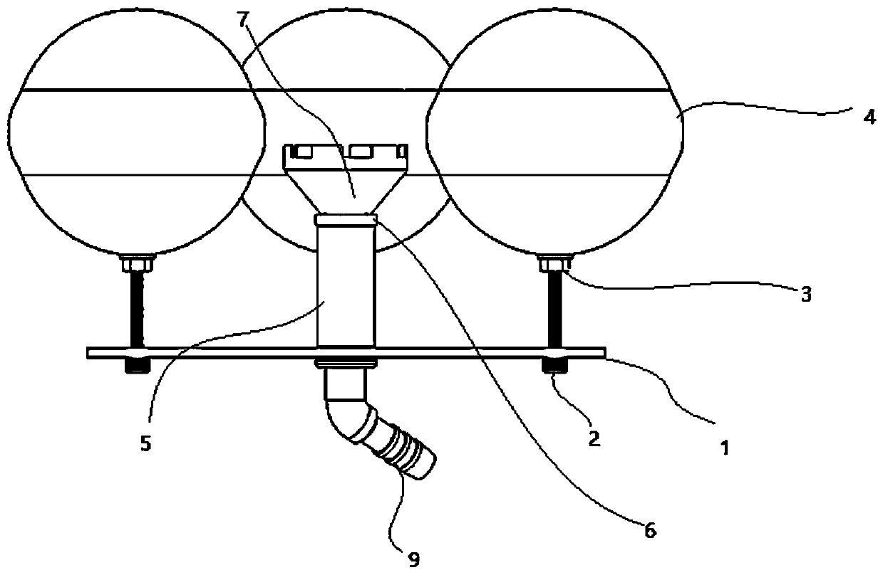
[0038] like Figure 1 to Figure 5 As shown, the device of the present invention comprises a disc-shaped bottom plate 1 , three floating balls 4 evenly distributed on the outer side of the bottom plate 1 , and the floating balls 4 are bolted to the bottom plate 1 . An oil-water separation chamber is pierced through the middle of the bottom plate 1, and the bottom end of the oil-water separation chamber is communicated with the suction conduit 10 (see Figure 9 and Figure 10 ), the suction conduit 10 is connected with a flow regulating valve 12 for regulating its flow (see Figure...


PUM


Abstract

The invention discloses a liquid absorbing floating ball device for oil-water separation. The liquid absorbing floating ball device for the oil-water separation comprises a bottom plate, a plurality of floating balls, an oil-water separating cavity, a sucking and pumping guide pipe and a flow regulating valve; the floating balls are movably connected with the bottom plate; the distance between thebottom plate and the floating balls is adjustable; the oil-water separating cavity is formed in the bottom plate in a penetrating manner; the oil-water separating cavity comprises a funnel-shaped upper cavity body; teeth-shaped grooves are annularly distributed in the top end of the upper cavity body; the sucking and pumping guide pipe is communicated with the oil-water separating cavity; the flow regulating valve is used for regulating the flow which passes through the sucking and pumping guide pipe. The device disclosed by the invention is easy to produce, process and manufacture, small insize, low in cost, high in oil-water separating efficiency, environment-friendly and low in energy consumption, is not required to be attended by specially-assigned persons. Vortex oil liquid is extremely easily produced by an oil liquid by the funnel-shaped upper cavity body of which the upper end is distributed with teeth-shaped groove annularly in a separating process; a separating process is continuous; an air suction phenomenon cannot be produced; the liquid absorbing floating ball device for the oil-water separation can be adapted to the environment to change different working conditions, and helps realize oil-water separating effectively and quickly.

Description

technical field [0001] The invention belongs to the technical field of oil-water mixture filtration treatment, and particularly relates to a liquid-absorbing floating ball device for oil-water separation. Background technique [0002] Oily waste liquid mainly comes from industrial sectors such as petroleum, petrochemical, steel, coking, gas generating stations, and mechanical processing. In the actual industrial production process, a large amount of oily waste liquid will be produced, and the problems involve a wide range of fields, such as cutting fluid waste liquid, cooling liquid waste liquid, lubricating oil waste liquid, and coating line degreasing tank waste liquid. If the oily waste liquid is not recycled, it will cause waste; if it is discharged into rivers, lakes or bays, it will pollute the water body and affect the survival of aquatic organisms; if it is used for agricultural irrigation, it will block soil gaps and hinder the growth of crops. After the oily waste...

Claims


Application Information

Patent Timeline
IPC IPC(8): B01D17/032
CPCB01D17/0214
Inventor 谭微熊康刘城淼
Owner SHANGHAI GREENSUN ENVIRONMENTAL PROTECTION TECH CO LTD
Learn More