Micro-tension automatic wire storing device for processing optical fibers and cables

A fiber optic cable, micro-tension technology, applied in the direction of transportation and packaging, delivery of filamentous materials, thin material processing, etc., can solve the mismatch between cable pay-off and take-up speed, cable tearing, inaccurate detection, etc. problem, achieve the effect of improving production and processing efficiency and saving space

Inactive Publication Date: 2019-08-27
JIANGSU HENGTONG PHOTOELECTRIC
View PDF5 Cites 0 Cited by
  • Summary
  • Abstract
  • Description
  • Claims
  • Application Information

AI Technical Summary

Problems solved by technology

However, when the existing cable storage device knows the cable take-up rate through the displacement sensor, there are problems of inaccurate detection and unstable signal, which leads to a mismatch between the pay-off and take-up speed of the cable, and the cable is pulled. And the problem of cable loosening occurs from time to time

Method used


Image

  • Micro-tension automatic wire storing device for processing optical fibers and cables
  • Micro-tension automatic wire storing device for processing optical fibers and cables
  • Micro-tension automatic wire storing device for processing optical fibers and cables

Examples


Embodiment 1

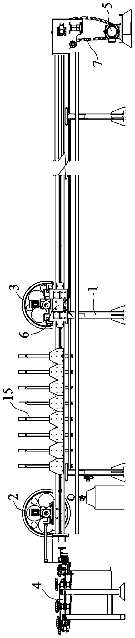
[0034] Embodiment 1: A micro-tension automatic wire storage device for optical fiber and cable processing, including a support 1, a first wire storage wheel set 2, a second wire storage wheel set 3, a guide mechanism 4 and a drive mechanism 5, the The first wire storage wheel group 2 and the second wire storage wheel group 3 are installed on the support 1, the guide mechanism 4 is located at one end of the support 1, and the driving mechanism 5 is arranged at the other end of the support 1;

[0035] The second wire storage wheel set 3 is movably mounted on the support 1 through a movable seat 6, and the driving mechanism 5 is connected with the movable seat 6 through a chain 7 for driving the second wire storage wheel set 3 in the Move on the support 1 along the length direction of the support 1 to approach or move away from the first line storage wheel set;

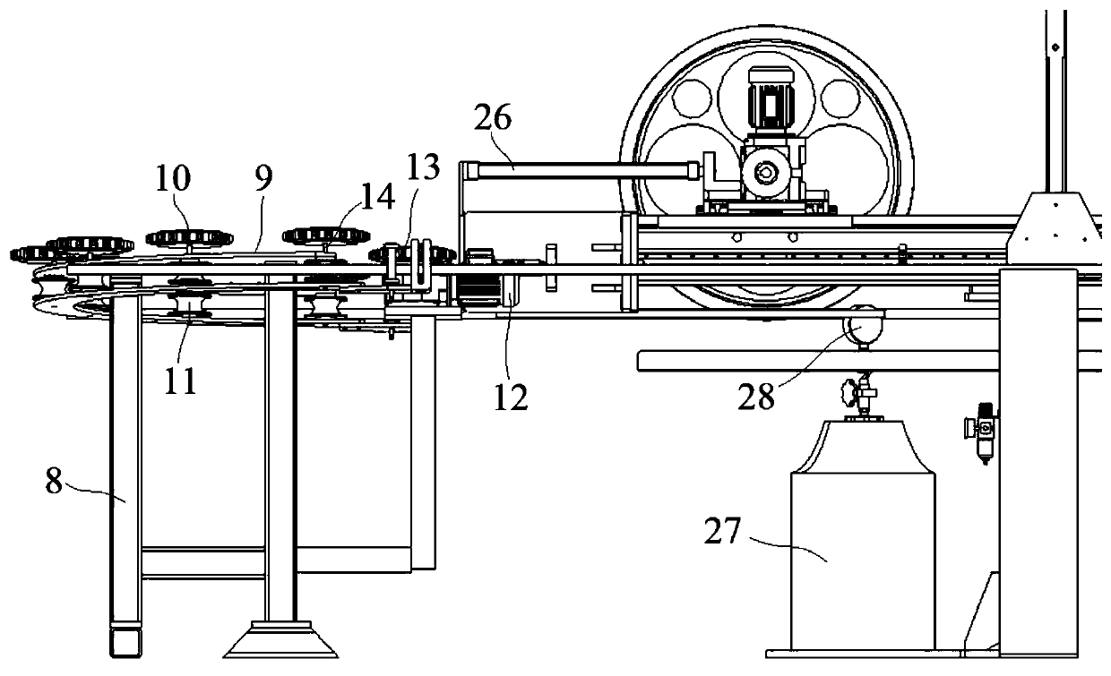
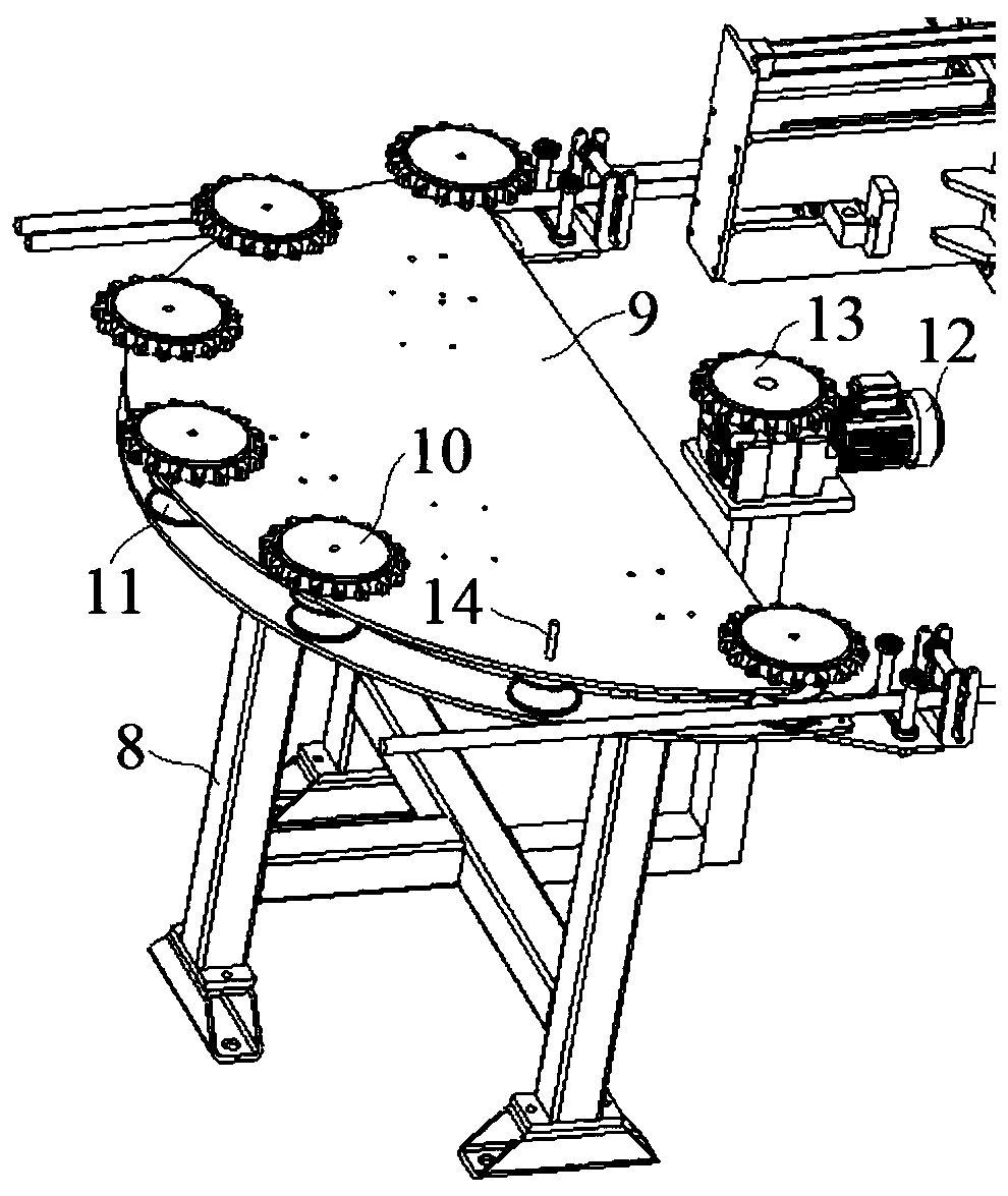
[0036] Described guiding mechanism 4 comprises base 8, the semicircle mounting plate 9 that is installed on the base 8...

Embodiment 2

[0041] Embodiment 2: A micro-tension automatic wire storage device for optical fiber and cable processing, including a support 1, a first wire storage wheel set 2, a second wire storage wheel set 3, a guide mechanism 4 and a drive mechanism 5, the The first wire storage wheel group 2 and the second wire storage wheel group 3 are installed on the support 1, the guide mechanism 4 is located at one end of the support 1, and the driving mechanism 5 is arranged at the other end of the support 1;

[0042] The second wire storage wheel set 3 is movably mounted on the support 1 through a movable seat 6, and the driving mechanism 5 is connected with the movable seat 6 through a chain 7 for driving the second wire storage wheel set 3 in the Move on the support 1 along the length direction of the support 1 to approach or move away from the first line storage wheel set;

[0043] Described guiding mechanism 4 comprises base 8, the semicircle mounting plate 9 that is installed on the base 8...


PUM


Abstract

The invention discloses a micro-tension automatic wire storing device for processing optical fibers and cables. The micro-tension automatic wire storing device for processing the optical fibers and cables comprises a support, a first wire storing wheel group, a second wire storing wheel group, a guiding mechanism and a driving mechanism, wherein the first wire storing wheel group and the second wire storing wheel group are mounted on the support; the driving mechanism is arranged at the other end of the support; the second wire storing wheel group is movably mounted on the support by means ofa movable seat; the driving mechanism is connected with the movable seat by means of a chain; at least one sliding rail is mounted at the part, on the support, below a mounting seat; a sliding block allowing the sliding rails to be embedded therein is mounted on the lower surface of the mounting seat; one side of the mounting seat is connected with a piston rod of an air cylinder; and a pressure stabilizing tank is connected with the air cylinder by means of a precision pressure regulating valve, and is used for providing constant thrust for the air cylinder. The micro-tension automatic wire storing device for processing the optical fibers and cables eliminates the static friction force between wheel discs and core shafts when cables generate side pressure on the wheel discs, so that the cables passing through the wheel discs keep constant tension without being influenced by the wheel discs, and the cable processing stability is ensured.

Description

technical field [0001] The invention relates to a micro-tension automatic wire storage device for optical fiber and cable processing, and belongs to the technical field of cable production equipment. Background technique [0002] In the field of photoelectric production, a cable storage device is usually installed between the cable production device and the take-up equipment to coordinate the pay-off and take-up speeds between the cable production device and the take-up equipment to keep them relatively steady state. The existing cable storage device senses the cable take-up rate through the displacement sensor, and then transmits the signal to the cable pay-off device, and then the cable pay-off device adjusts the pay-off rate according to the change of the signal, so that the cable The cable pay-off rate and the cable take-up rate remain relatively stable. However, when the existing cable storage device knows the cable take-up rate through the displacement sensor, there ...

Claims


Application Information

Patent Timeline
Patent Type & Authority Applications(China)
IPC IPC(8): B65H49/38
CPCB65H49/38B65H2701/34
Inventor 李兴进轩传吴江荣李龙闵玥李成飞张鑫元盛文琴嵇德海孙建
Owner JIANGSU HENGTONG PHOTOELECTRIC
Why Eureka
Try Eureka