Optical light splitting device and light splitting photovoltaic system

A spectroscopic device and optical technology, applied in optics, photovoltaic power generation, photovoltaic modules, etc., can solve the problems of Ge sub-cell not reaching the best working state, large current, and insufficient use of long-wavelength light.

Pending Publication Date: 2019-08-27
PEKING UNIV SHENZHEN GRADUATE SCHOOL
View PDF0 Cites 1 Cited by
  • Summary
  • Abstract
  • Description
  • Claims
  • Application Information

AI Technical Summary

Problems solved by technology

Under the standard spectral distribution of AM1.5d, Ga 0.50 In 0.50 P subcell and Ga 0.99 In 0.01 The current obtained by the As sub-battery is relatively matched, and the current obtained by the Ge sub-battery is relatively large. This current mismatch will cause the Ge sub-battery to fail to achieve the best working condition, so that the long-wavelength light is not fully utilized.

Method used


Image

  • Optical light splitting device and light splitting photovoltaic system
  • Optical light splitting device and light splitting photovoltaic system
  • Optical light splitting device and light splitting photovoltaic system

Examples


Embodiment 1

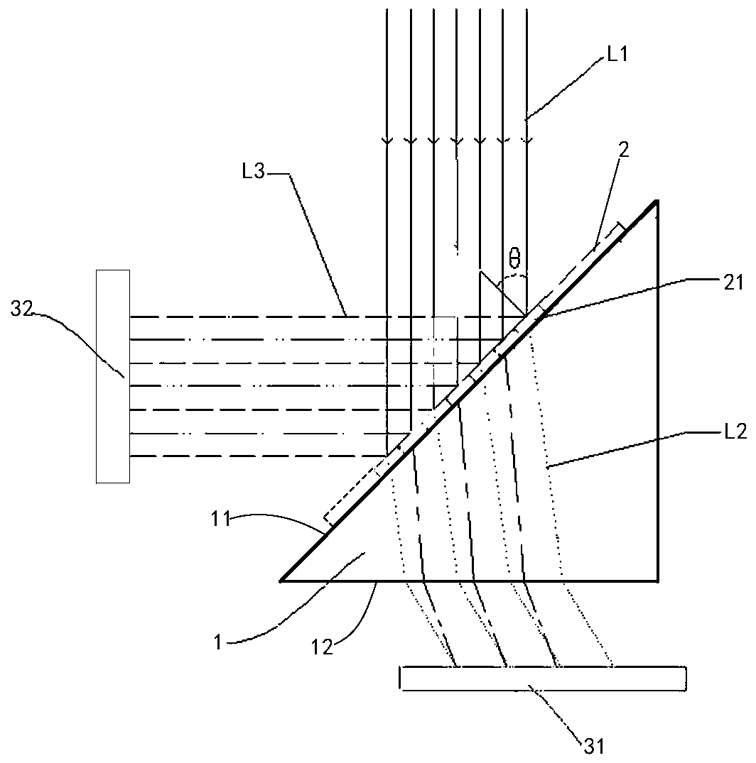
[0036] Please refer to figure 1 , the present application discloses an optical spectroscopic device, which mainly includes an optical substrate 1 and a plurality of optical films 2, which will be described separately below.

[0037] The optical base 1 includes an incident surface 11 and a corresponding exit surface 12, so that part of the incident light can enter from the incident surface 11 and exit from the exit surface 12.

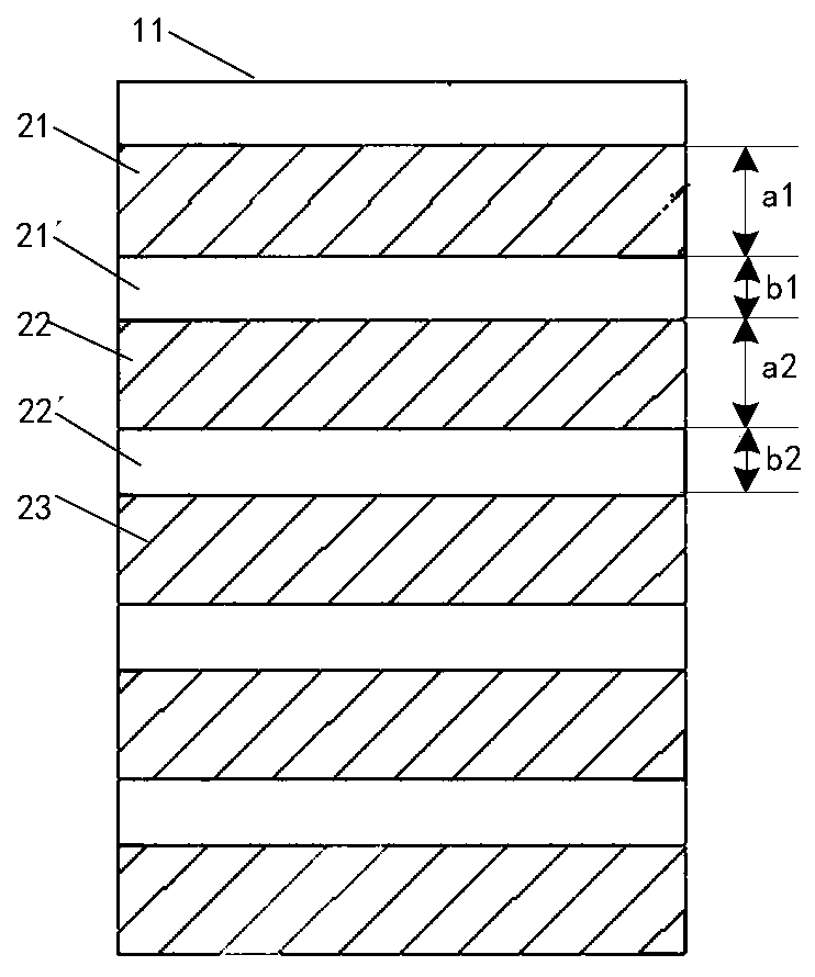
[0038] A plurality of optical films 2 are arranged and distributed on the incident surface 11, and each optical film forms a spectroscopic area with a predetermined spectroscopic performance, which is used to divide the incident light reaching the spectroscopic area into transmitted light transmitted by a specific band of light and blocked by other bands of light of reflected light. Thus, the transmitted light of each optical film enters along the incident surface 11 and exits through the exit surface 12. The exit surface 12 in this embodiment is used ...

Embodiment 2

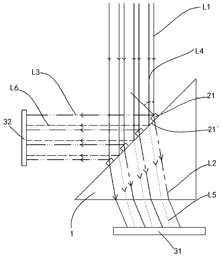
[0062] Please refer to Figure 6 , the present application discloses a spectrophotovoltaic system, which includes the optical reflective device disclosed in Embodiment 1 above, and also includes a first photovoltaic cell 51 and a second photovoltaic cell 52.

[0063] The first photovoltaic cell 51 is arranged in the first mapping area 31 formed by the optical spectroscopic device, and is used to receive the transmitted light reaching the first mapping area 31.

[0064] The second photovoltaic cell 52 is arranged in the second mapping area 32 formed by the photovoltaic spectroscopic device, and is used to receive the reflected light 32 reaching the second mapping area.

[0065] Further, the incident surface 11 of the optical substrate 1 in the split photovoltaic system is used to face the light source 6, so that the angle θ formed between the incident light emitted by the light source and the normal line of the incident surface 11 satisfies 0°<θ<90° , it is preferable to set t...


PUM


Abstract

The invention discloses an optical light splitting device and a light splitting photovoltaic system. The optical light splitting device comprises an optical substrate and a plurality of optical thin films; the optical thin films form light splitting areas with different light splitting properties respectively; and the light splitting area formed by each optical thin film transmits incident light of one of a short wave band, a medium wave band and a long wave band. The combination of light rays of different wave bands is achieved through the plurality of optical thin films and the optical substrate, and the requirement for flexibly adjusting a light transmission ratio is met, so that photovoltaic cells with different PN junctions arranged in mapping areas can obtain solar spectral bands matched with the photovoltaic cells and a proper amount of solar radiation energy, the currents output by the PN junctions on the photovoltaic cells are uniformly output, and the photoelectric conversionefficiency of the solar cells is further improved; and especially for the multi-junction photovoltaic cells, the light splitting photovoltaic system can greatly improve the photoelectric conversion efficiency of the multi-junction photovoltaic cells.

Description

technical field [0001] The invention relates to the technical field of photovoltaic power generation, in particular to an optical light splitting device and a light splitting photovoltaic system. Background technique [0002] After decades of development, solar power generation technology has established its important position in the field of new energy. Photovoltaic cells are the core devices of solar power generation, and their photoelectric conversion efficiency directly affects the performance of the entire power generation system. How to improve the photoelectric conversion efficiency of photovoltaic cells and the power generation efficiency of photovoltaic systems has always been the goal pursued by researchers in the field of solar power generation. [0003] As we all know, the core of a solar cell is a PN junction, and a PN junction corresponds to a fixed band gap, which can only absorb photons in a specific wavelength range and has the highest absorption efficiency ...

Claims


Application Information

Patent Timeline
IPC IPC(8): G02B27/10H02S40/20
CPCG02B27/1006H02S40/20Y02E10/50
Inventor 金鹏张军斌黄创军
Owner PEKING UNIV SHENZHEN GRADUATE SCHOOL
Why Eureka
Try Eureka