High-efficiency scraper blade film evaporator

A thin-film evaporator and evaporator technology, which is applied in evaporator accessories, evaporator adjustment/control, evaporation, etc., can solve the problems that the scraper cannot be adjusted, reduce the evaporation efficiency, etc., and achieve a stable and reliable installation structure and reduce production costs. Effect

Inactive Publication Date: 2019-08-30
WUXI KELUNDA CHEM & THERMAL EQUIP
View PDF5 Cites 2 Cited by
  • Summary
  • Abstract
  • Description
  • Claims
  • Application Information

AI Technical Summary

Problems solved by technology

[0003] Aiming at the technical problem that the scraper of the existing scraper type thin film evaporator cannot be adjusted after installation, and once it wears out, a new scraper must be replaced, otherwise the evaporation efficiency will be reduced. The present invention provides a high-efficiency scraper thin film evaporator, The scraper can be adjusted, just adjust the scraper to the proper position after wear and tear, no need to replace, and can ensure efficient evaporation

Method used


Image

  • High-efficiency scraper blade film evaporator
  • High-efficiency scraper blade film evaporator
  • High-efficiency scraper blade film evaporator

Examples


Embodiment Construction

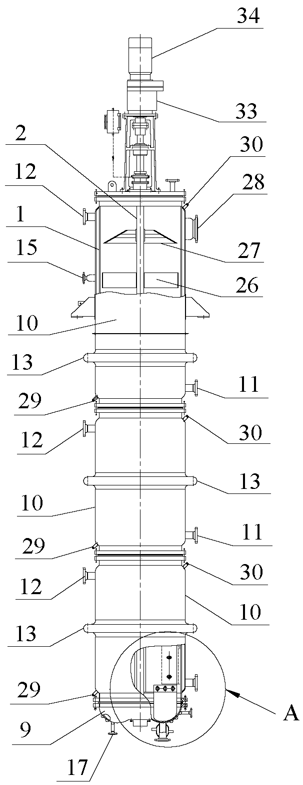
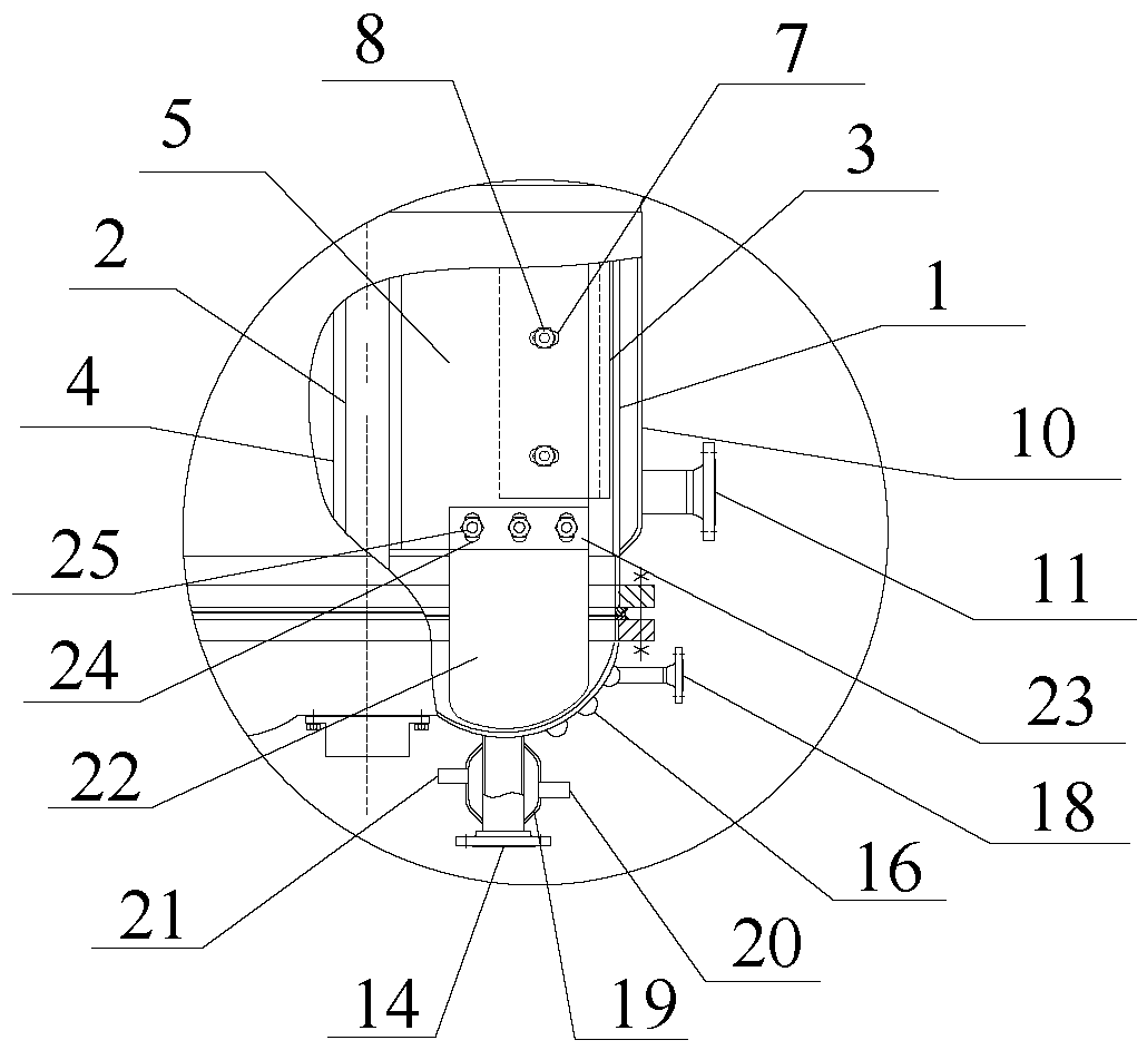
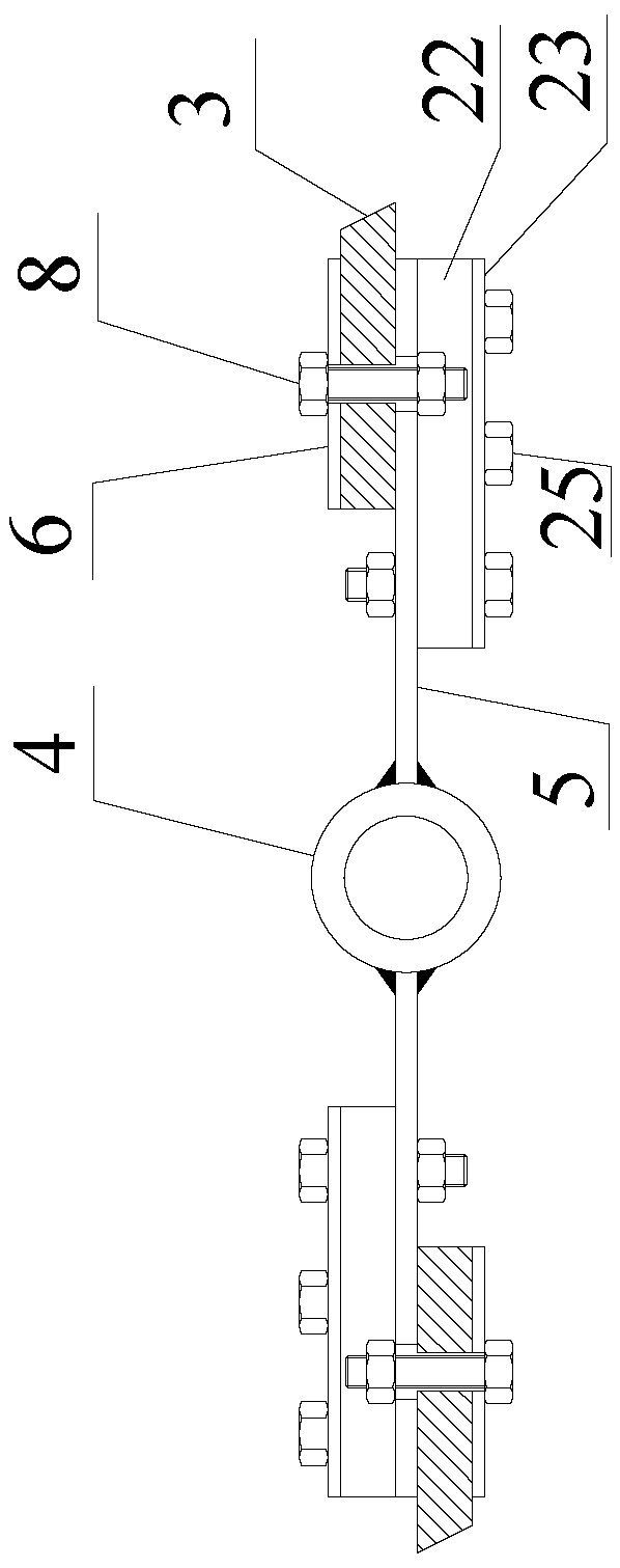
[0022] See Figure 1 to Figure 3 , a high-efficiency scraper film evaporator of the present invention, which includes an evaporator cylinder 1, a rotating shaft 2, a scraper 3, a scraper frame and a pressure plate 6, the scraper frame includes a shaft sleeve 4 and a support plate 5, and the shaft sleeve 4 Set and fixed on the rotating shaft 2, there are at least two support plates 5 arranged evenly along the circumference of the sleeve 4, one end of the support plate 5 is welded to the side wall of the sleeve 4, and the length direction of the support plate 5 is parallel In the axial direction of the shaft sleeve 4, the width direction is parallel to the radial direction of the shaft sleeve 4; the side of the support plate 5 away from the shaft sleeve 4 is evenly distributed with waist-shaped holes 7 along its length direction, and the length direction of the waist-shaped holes 7 Parallel to the radial direction of the shaft sleeve 4; the pressure plate 6 and the support plate...


PUM


Abstract

The invention provides a high-efficiency scraper blade film evaporator, which can solve the problem that the scraper blade of the existing scraper blade type film evaporator can not be adjusted afterinstallation, and the scraper blade has to be replaced with a new scraper blade after being worn, or otherwise the evaporation efficiency may be reduced. The high-efficiency scraper blade film evaporator comprises an evaporator cylinder, a rotating shaft, a scraper blade, a scraper blade frame and a pressure plate. The scraper blade frame comprises a shaft sleeve and a support plate; the shaft sleeve sleeves the rotating shaft and is fixed to the rotating shaft; the support plate is uniformly arranged along the circumferential direction of the shaft sleeve; one end of the support plate is fixed to the side wall of the shaft sleeve; the length direction of the support plate is parallel to the axial direction of the shaft sleeve; the width direction of the support plate is parallel to the radial direction of the shaft sleeve; the side, away from the shaft sleeve, of the support plate is provided with a kidney slot; the length direction of the kidney slot is parallel to the radial direction of the shaft sleeve; the pressure plate is arranged in one-to-one correspondence with the support plate; the scraper blade is sandwiched between the pressure plate and the support plate, and the pressure plate, the scraper blade, and the support plate are tightened by a bolt inserted in the kidney slot; Upon tightening; and one end, away from the shaft sleeve, of the scraper blade extends out of the pressure plate and the support plate, a uniform gap is preserved with the inner wall of the evaporator cylinder.

Description

technical field [0001] The invention relates to the field of evaporators, in particular to a high-efficiency scraper film evaporator. Background technique [0002] Thin film evaporators can be divided into rising film evaporators, falling film evaporators and scraper evaporators according to the cause of film formation and flow direction. The raw material liquid in the scraper evaporator flows from top to bottom Under the action of self-weight, a downward-swirling film is formed on the inner wall of the evaporator shell, and at the same time, it exchanges heat with the inner wall of the shell. The final finished liquid is discharged from the bottom of the evaporator, and the secondary steam is discharged from the upper part of the evaporator after gas-liquid separation. Scraped evaporators are widely used in distillation, concentration, degassing and other fields. However, the scraper type thin film evaporator currently on the market has a relatively simple structure. The s...

Claims


Application Information

Patent Timeline
Patent Type & Authority Applications(China)
IPC IPC(8): B01D1/22B01D1/30
CPCB01D1/0041B01D1/0082B01D1/225B01D1/30B01D1/305
Inventor 董建平
Owner WUXI KELUNDA CHEM & THERMAL EQUIP
Why Eureka
Try Eureka