Installing structure of spline shaft with attached cutting head

A technology of installation structure and spline shaft, which is applied to metal processing equipment, metal processing mechanical parts, large fixed members, etc., can solve the problem of affecting the normal operation of the gears in the box of the additional cutting head, the automatic replacement of the additional cutting head cannot be completed, and the transmission Unreasonable assembly design of shaft and bevel gear, etc., to achieve the effect of ensuring processing stability, simple structure and reliable installation structure

Inactive Publication Date: 2010-12-08
无锡桥联数控机床有限公司
View PDF4 Cites 0 Cited by
  • Summary
  • Abstract
  • Description
  • Claims
  • Application Information

AI Technical Summary

Problems solved by technology

[0003] In the prior art, due to the unreasonable assembly design of the transmission shaft and the bevel gear, the connecting screws are easily loosened under the action of inertial force under the action of additional cutting head emergency stop, forward and reverse start, etc.; If it falls off after being loose, it will easily affect the normal operation of the gears in the additional cutting head box, and even cause damage to the transmission bevel gear.
At the same time, due to the loosening of the connecting screws, the transmission shaft lacks axial movement constraints, so that when the additional cutting head is automatically replaced, when the broach claws are pulled up, only the transmission shaft is pulled up, and the entire additional cutting head does not work. The purpose of the position, so that the action of automatically changing the additional cutting head cannot be completed

Method used


Image

  • Installing structure of spline shaft with attached cutting head
  • Installing structure of spline shaft with attached cutting head

Examples


Embodiment Construction

[0010] Below the present invention will be further described in conjunction with the embodiment in the accompanying drawing:

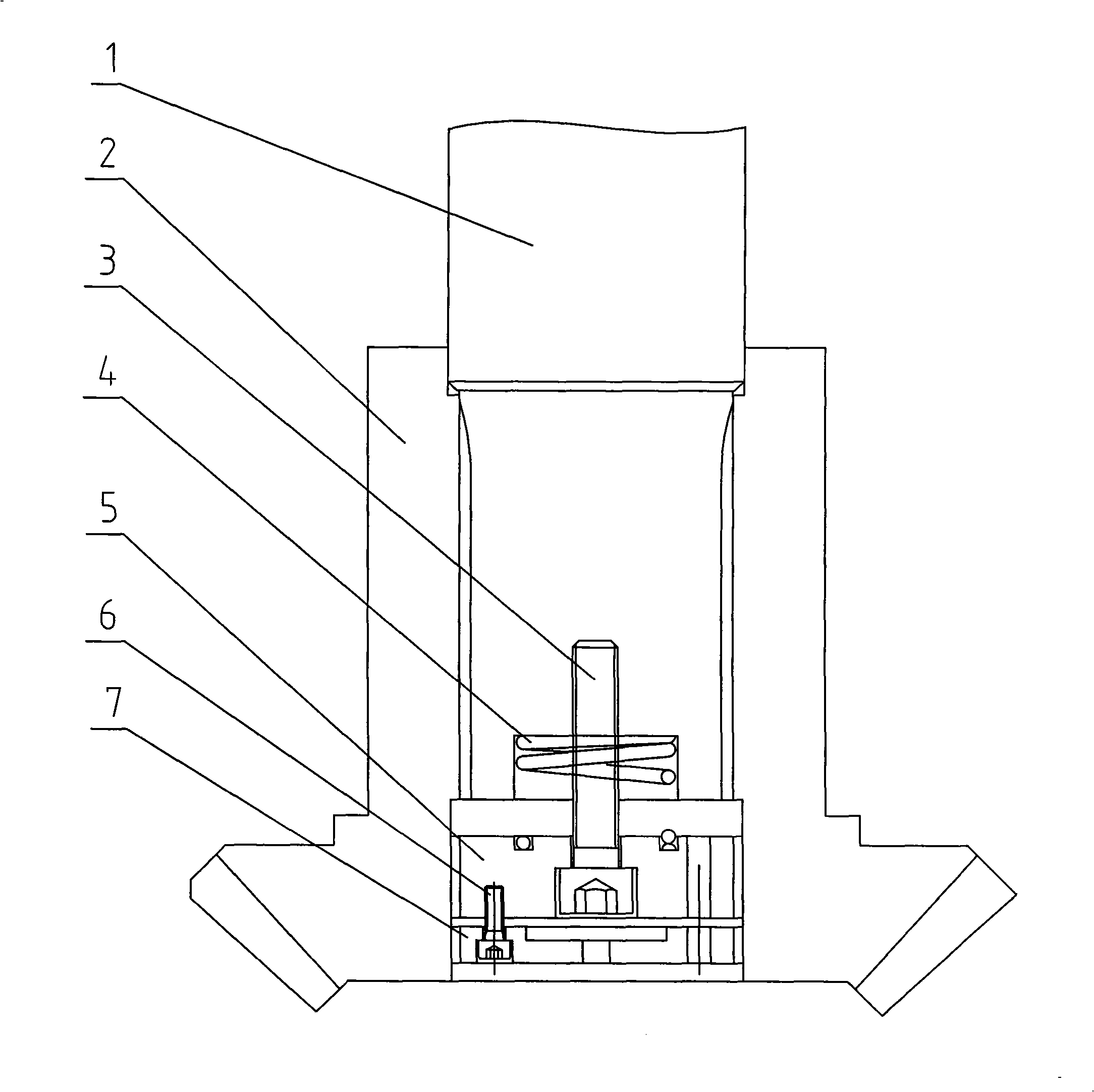
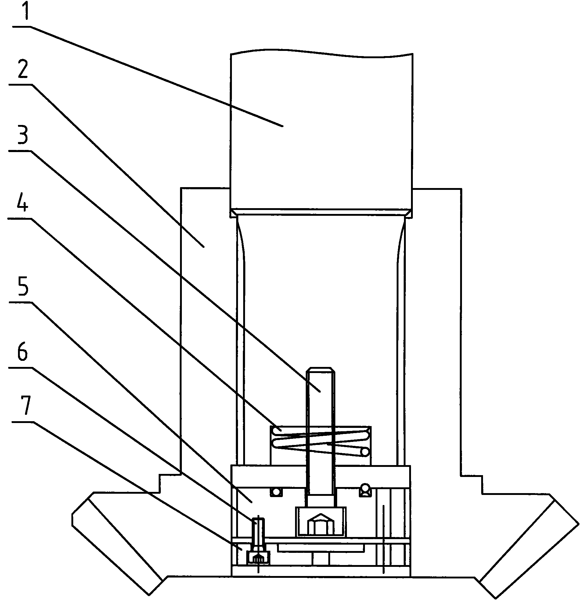
[0011] Such as figure 1 As shown, it includes a spline shaft 1, a bevel gear 2, a connecting screw 3, a spring 4, a nut 5, a screw 6 and a lock nut 7, etc.

[0012] In the present invention, the internal spline is processed at the rear section of the core of the bevel gear 2 axis, and is connected with the spline shaft 1 to transmit cutting power; the thread is processed at the front section of the core of the bevel gear 2 axis. When assembling, first place the spring 4 in the circular groove at the end of the spline shaft 1; screw the nut 5 into the threaded part of the bevel gear 2, and compress the spring 4; when the nut 5 is screwed to the designed position, screw in the connecting screw 3, and The nut 5 is connected to the spline shaft 1; under the action of the spring force of the spring 4, the nut 5 and the spline shaft 1 have a tendency to mov...


PUM


Abstract

The invention relates to an installing structure of a spline shaft with an attached cutting head, comprising the spline shaft and a bevel gear, and an inner spline is machined at the back section of ashaft core part of the bevel gear and connected with the spline shaft. The installing structure is characterized in that a thread is machined at the front section of the shaft core part of the bevelgear, a spring is arranged in a circular groove at the end part of the spline shaft; a nut is screwed in the thread part of the bevel gear which compresses the spring; a connecting screw is screwed into connect the nut and the spline shaft, and then a lock nut is screwed in to connect the nut and the lock nut. The installing structure has simple structure, reasonability and convenient installation, provides the reliable installing structure of the spline shaft, ensures the stable connection between a drive shaft and the bevel gear, is conductive to smooth automatic replacement of the attachedcutting head by a machining center, reduces the accident rate of the attached cutting head, ensures the machining stability of the attached head and improves the machining efficiency.

Description

technical field [0001] The invention relates to a spline shaft installation structure of an additional cutting head, in particular, it is suitable for the installation of the main drive spline shaft of an additional cutting head in a pentahedron gantry machining center, and belongs to the technical field of mechanical structures. Background technique [0002] With the rapid development of my country's machinery industry, especially the development of heavy industry, there is an increasing demand for high-precision metal processing equipment such as pentahedron gantry machining centers. Pentahedron gantry machining centers are developed on the basis of gantry machining centers. A multi-functional CNC machine tool, through automatic replacement of various additional cutting heads, can realize multi-faceted processing of large mechanical parts. Usually, all or most of the processing procedures of large mechanical parts can be completed in one clamping, thus greatly reducing Impro...

Claims


Application Information

Patent Timeline
Patent Type & Authority Patents(China)
IPC IPC(8): B23Q1/70
Inventor 黄俊桂徐彬单文勇周晖叶穗
Owner 无锡桥联数控机床有限公司
Why Eureka
Try Eureka