Method for machining fan-shaped plate outer circle by utilizing split base plate

A fan-shaped plate and split-type technology, which is applied to metal processing equipment, metal processing machine parts, manufacturing tools, etc., can solve problems such as unreliable positioning, out-of-tolerance dimensions of four-piece fan-shaped plates, and inability to ensure assembly accuracy. Achieve the effect of solving the out-of-tolerance of the outer circle size, avoiding electric welding, and ensuring the stability of processing

Active Publication Date: 2014-01-22
MCC SFRE HEAVY IND EQUIP
View PDF5 Cites 3 Cited by
  • Summary
  • Abstract
  • Description
  • Claims
  • Application Information

AI Technical Summary

Problems solved by technology

[0004] The purpose of the present invention is to provide a method for processing the outer circle of a fan-shaped plate by using a split backing plate, which solves the problem of four-piece fan-shaped plate outer circles due to the unreliable positioning of the fan-shaped plate and the main shaft in the prior art during the manufacturing process of the fan-shaped plate The size is out of tolerance, and the assembly accuracy cannot be guaranteed

Method used


Image

  • Method for machining fan-shaped plate outer circle by utilizing split base plate
  • Method for machining fan-shaped plate outer circle by utilizing split base plate
  • Method for machining fan-shaped plate outer circle by utilizing split base plate

Examples


Embodiment Construction

[0022] The present invention will be described in detail below in conjunction with the accompanying drawings and specific embodiments.

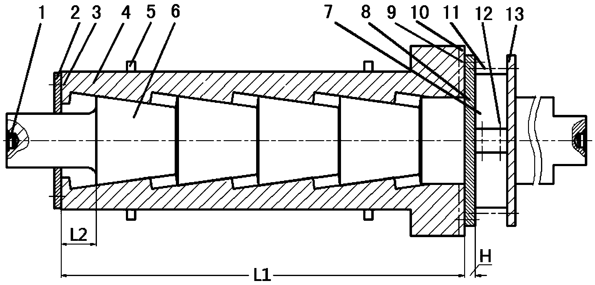
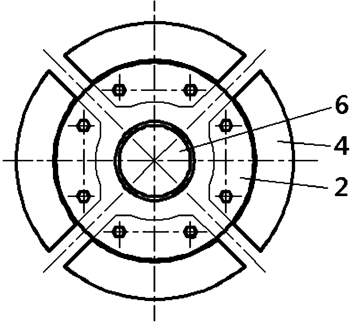
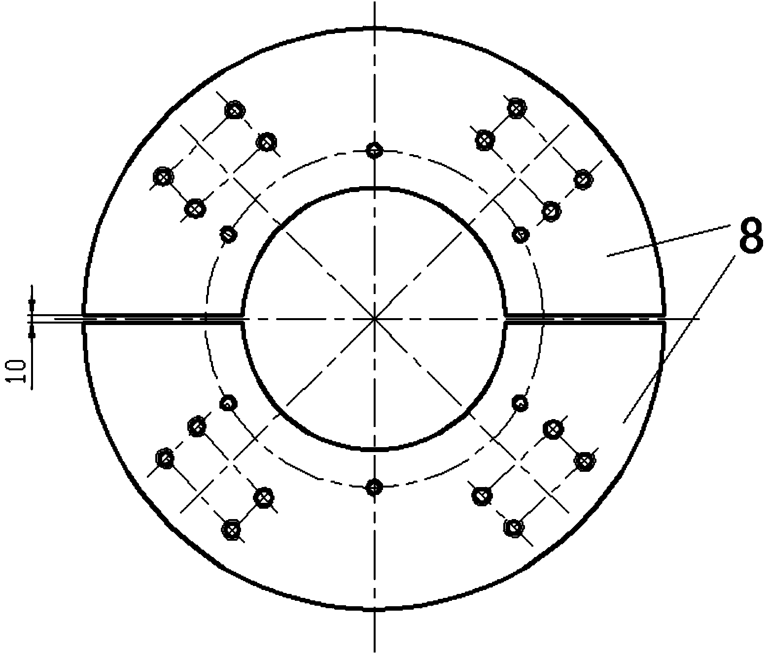
[0023] like figure 1 and figure 2 As shown, the structure of the split backing plate positioning device that the method of the present invention relies on includes a main shaft 6, an insertion plug 1 is installed in the center holes at both ends of the main shaft 6, and four fan-shaped parts are installed around the main shaft 6. Plate 4, the outer surface of four fan-shaped plates 4 is provided with at least two clamps 5; on the shoulder side of the main shaft 6 pyramids ( figure 1 On the right side) there is a positioning body 7, and a tooling backing plate 10 is respectively arranged in the end face grooves of the four fan-shaped plates 4 facing the positioning body 7, and a tooling backing plate 10 is provided between the tooling backing plate 10 and the inner end surface of the positioning body 7 Backing plate 8, backing plate 8 is fi...


PUM


Abstract

The invention discloses a method for machining a fan-shaped plate outer circle by utilizing a split base plate. The method comprises the steps that a positioning body is combined on a main shaft, an upper lathe is positioned through inserting blocks which are arranged at the two ends, the two end faces of the positioning body are machined, the length size L of the installing space of fan-shaped plates is controlled in the range of +/-0.2mm, the two end faces of the positioning body are perpendicular to the axis of the main shaft, and the two end faces of the positioning body are parallel to each other. The four fan-shaped plates are arranged into the main shaft and are respectively clamped through the cooperation of two sets of clamps and jack screws, the base plate and the large ends of the fan-shaped plates are fixed through a tool base plate, and the small ends of the fan-shaped plates are connected with a shaft end baffle. A pull plate is connected with the base plate through a long screw rod but not held tightly, the planeness of the end face of the base plate is checked, and gaps between the two end faces of the base plate and the fan-shaped plates and between the two end faces of the base plate and the end face of the positioning body are rechecked. The long screw rod is held tightly, and the outer circle of the fan-shaped plates is machined. The method solves the problem that the positioning cannot be achieved in the radial direction when the outer circle of the fan-shaped plates is machined.

Description

technical field [0001] The invention belongs to the technical field of metallurgical processing and manufacturing, and relates to a method for processing the outer circle of a fan-shaped plate by using a split backing plate. Background technique [0002] In the field of metallurgical equipment manufacturing, uncoilers and coiler reels are the core equipment of the plate (strip) rolling and post-processing production line. Due to their complex structure and difficult manufacturing, the manufacturing capacity of reels has always been a measure of an enterprise. A measure of manufacturing capacity, the fan-shaped plate is the core load-bearing part in the reel, and its manufacturing accuracy has always been the most critical factor in determining the manufacturing accuracy of the reel. [0003] At present, the outer circle of the fan-shaped plate is profiling processed by a CNC milling machine and the combination of the main shaft, the fan-shaped plate and the hollow sleeve is ...

Claims


Application Information

Patent Timeline
Patent Type & Authority Applications(China)
IPC IPC(8): B23Q3/06
CPCB23Q3/12B24B41/06
Inventor 杨学军李向宁
Owner MCC SFRE HEAVY IND EQUIP
Why Eureka
Try Eureka