Method for machining bottle-shaped shaft of large pumped storage generator motor

A technology for generating electric motors and pumped water storage, which is applied to the rotating parts of the magnetic circuit, the shape/style/structure of the magnetic circuit, etc., which can solve the problems of affecting the processing accuracy and increasing the processing difficulty, so as to meet the requirements of high precision and improve the processing accuracy , the effect of reducing the error

Active Publication Date: 2020-07-17
DONGFANG ELECTRIC MACHINERY
View PDF7 Cites 3 Cited by
  • Summary
  • Abstract
  • Description
  • Claims
  • Application Information

AI Technical Summary

Problems solved by technology

[0005] This patent document discloses a large-scale pumped storage generator integral bottle-shaped shaft welding manufacturing method, which uses narrow-gap automatic argon arc welding equipment to perform single-sided welding on the narrow gap slope formed by the bottle-shaped shaft section, and welds the arc-shaped transition zone When the part reaches the design thickness, the paired bottle-shaped shaft section is placed vertically on the turntable, and the narrow-gap automatic argon arc welding equipment is aligned with the arc-shaped transition area, and the turntable drives the paired bottle-shaped shaft section Realize circular welding, this kind of welding is carried out by vertical method, because only one end has a frame, which greatly increases the difficulty of processing and affects the processing accuracy

Method used


Image

  • Method for machining bottle-shaped shaft of large pumped storage generator motor
  • Method for machining bottle-shaped shaft of large pumped storage generator motor
  • Method for machining bottle-shaped shaft of large pumped storage generator motor

Examples


Embodiment 1

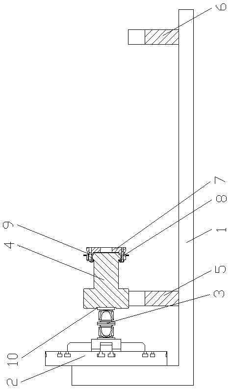
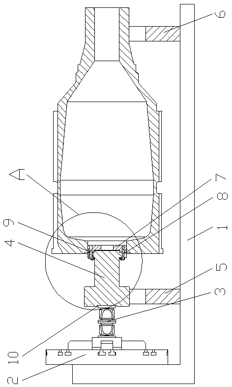
[0034] see Figure 1-Figure 3 , a method for processing a bottle-shaped shaft of a large-scale pumped-storage generator motor, comprising the following steps:

[0035] a. Install the end face of the big end of the bottle-shaped shaft on the boring machine on the working platform, and bore the matching hole between the center of the big end and the transition connecting plate 7;

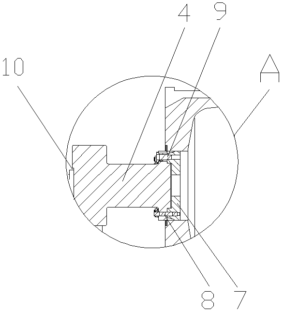
[0036] b. Turning the outer circle of the transition connecting plate 7 and the welding groove, installing and welding the transition connecting plate 7 into the center hole of the big end of the bottle shaft, boring and processing the transition connecting plate 7 and the process dummy shaft to coordinate the positioning seam and transition connection Plate 7 flange joint screw holes and positioning pin 9 holes;

[0037] c. The flange joint hole and locating pin 9 holes of the flange matching the dummy shaft of the boring process and the transition connecting plate 7, install the dummy shaft of the ...

Embodiment 2

[0042] see Figure 1-Figure 3 , a method for processing a bottle-shaped shaft of a large-scale pumped-storage generator motor, comprising the following steps:

[0043] a. Install the end face of the big end of the bottle-shaped shaft on the boring machine on the working platform, and bore the matching hole between the center of the big end and the transition connecting plate 7;

[0044] b. Turning the outer circle of the transition connecting plate 7 and the welding groove, installing and welding the transition connecting plate 7 into the center hole of the big end of the bottle shaft, boring and processing the transition connecting plate 7 and the process dummy shaft to coordinate the positioning seam and transition connection Plate 7 flange joint screw holes and positioning pin 9 holes;

[0045] c. The flange joint hole and locating pin 9 holes of the flange matching the dummy shaft of the boring process and the transition connecting plate 7, install the dummy shaft of the ...

Embodiment 3

[0051] see Figure 1-Figure 3 , a method for processing a bottle-shaped shaft of a large-scale pumped-storage generator motor, comprising the following steps:

[0052] a. Install the end face of the big end of the bottle-shaped shaft on the boring machine on the working platform, and bore the matching hole between the center of the big end and the transition connecting plate 7;

[0053] b. Turning the outer circle of the transition connecting plate 7 and the welding groove, installing and welding the transition connecting plate 7 into the center hole of the big end of the bottle shaft, boring and processing the transition connecting plate 7 and the process dummy shaft to coordinate the positioning seam and transition connection Plate 7 flange joint screw holes and positioning pin 9 holes;

[0054] c. The flange joint hole and locating pin 9 holes of the flange matching the dummy shaft of the boring process and the transition connecting plate 7, install the dummy shaft of the ...


PUM


Abstract

The invention discloses a method for machining a bottle-shaped shaft of a large pumped storage generator motor, and belongs to the technical field of motor shaft machining. The method is characterizedby comprising the following steps of a, boring a matching hole of the center of a large end and a transition connecting plate; b, turning an outer circle and a welding groove of the transition connecting plate, and assembling and welding the transition connecting plate into a shaft center hole in the large end of the bottle-shaped shaft; c, mounting a process dummy shaft at the large end of the bottle-shaped shaft; d, turning the process dummy shaft; e, on a working platform of a numerical control boring machine, erecting and installing the process dummy shaft to be parallel to the numericalcontrol boring machine by using angle iron, pressing a workpiece, checking by using a height gauge according to a line, pressing a gauge on the lower side surface of the machined groove by using a dial gauge, moving the machine tool away along an X axis, checking by using the height gauge according to the line, and machining a magnet yoke key groove to obtain a bottle-shaped shaft finished product. The chuck precision of a horizontal lathe does not affect the rotation center of the bottle-shaped shaft, the machining difficulty is reduced, the machining stability is guaranteed, the machining precision is improved, and machining operation is more convenient.

Description

technical field [0001] The invention relates to the technical field of motor shaft processing, in particular to a method for processing a bottle-shaped shaft of a large-scale pumped-storage generator motor. Background technique [0002] The bottle-shaped shaft of the pumped storage generator motor is welded into an integral structure by the upper end shaft and the rotor bracket. There are multiple ribs and yoke keyways on the circumference. Because the outer circle has vertical ribs, the bottle-shaped shaft is similar to the conventional shaft. Ratio, the position of no rack mouth can be set. The large end face of the bottle-shaped shaft has end face runout and the seam has circular runout requirements, and the requirements for the chord distance between the keyways of the yoke of the vertical bar and the verticality of the vertical bar are high. There are many vertical ribs on the outer circle of the bottle-shaped shaft, which cannot be used as a frame opening during turni...

Claims


Application Information

Patent Timeline
Patent Type & Authority Applications(China)
IPC IPC(8): B23P15/00H02K1/22
CPCB23P15/00H02K1/22
Inventor 杨悦伟谢贤斌
Owner DONGFANG ELECTRIC MACHINERY
Why Eureka
Try Eureka