A street lamp installation device and installation method thereof

A technology for installing devices and street lamps, which is applied to hoisting devices, hoisting devices, towers, etc., can solve the problems of dangerous construction process and unstable structure, and achieve the effect of improving safety, ensuring stability and uniform force.

Active Publication Date: 2020-12-11
华体智城系统集成有限公司
View PDF2 Cites 5 Cited by
  • Summary
  • Abstract
  • Description
  • Claims
  • Application Information

AI Technical Summary

Problems solved by technology

[0005] However, the above-mentioned installation methods are to directly fix the street lamp, and then rotate it 90° around a rotating shaft, so that the street lamp changes from a horizontal state to a vertical state, so that workers can install it. This method is used to flip the street lamp When the main force point is at the rotating shaft, the force is relatively concentrated, the structure has the disadvantage of instability, and there is still a certain degree of danger in the construction process.

Method used


Image

  • A street lamp installation device and installation method thereof
  • A street lamp installation device and installation method thereof
  • A street lamp installation device and installation method thereof

Examples


Embodiment 1

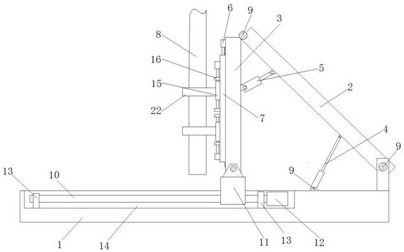
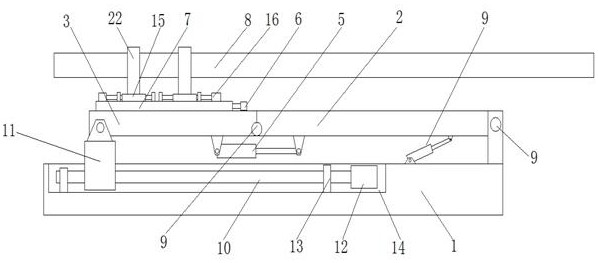
[0043] A street lamp installation device, including a base 1, a support I2, a support II3, a driving device I and a driving device II, the base 1 is in a "concave" shape, one end of the support I2 is hinged to the base 1, and the support I2 The other end of the drive device I is hinged to one end of the support member II3, one end of the drive device I is hinged to the base 1, and the other end is hinged to the support member I2, the drive device I can drive the support member I2 to rotate, and the two ends of the drive device II are respectively connected to the support Part I2 and support part II3 are hinged, and the driving device II can drive support part I2 and support part II3 to rotate around the hinge between support part I2 and support part II3, and a guide device is provided at the other end of support part II3 , the guiding device is in contact with the base 1, the guiding device can slide along the base 1, a sliding plate 7 is installed on the support member II3, th...

Embodiment 2

[0061] This embodiment is basically the same as Embodiment 1, the difference is that the driving devices I, II and III are pneumatic driving devices.

[0062] Wherein, the driving device IV can also be a pneumatic or hydraulic driving device. In actual use, the air cylinder or hydraulic cylinder is fixed on the base 1, and then the movable end of the air cylinder or hydraulic cylinder is connected to the guide device, that is, it is connected to the straight line Bearings are connected.

Embodiment 3

[0064] This embodiment is basically the same as Embodiment 1, the difference is that the guide device includes guide rails and rollers, the guide rails are installed on the base 1, the rollers are installed at the end of the support member II3, and the rollers can be Roll on rails.

[0065] In this way, the roller is connected to the lead screw nut 11; in actual use, the rotating shaft 9 of the roller can be extended and then connected to the lead screw nut 11.


PUM


Abstract

The invention discloses a mounting device of a street lamp. The mounting device is characterized by comprising a base, a supporting piece I, a supporting piece II, a driving device I and a driving device II, wherein the base is in a concave shape, one end of the supporting piece I is hinged to the base, the other end of the supporting piece I is hinged to one end of the supporting piece II, one end of the driving device I is hinged to the base, the other end of the driving device I is hinged to the supporting piece I, the driving device I can drive the supporting piece I to rotate, and the twoends of the driving device II are hinged to the supporting piece I and the supporting piece II. The invention further discloses a mounting method of the street lamp. According to the mounting deviceand the mounting method, the street lamp can be mounted, the safety of the mounting process is higher, accidents can be effectively avoided, and the safety of workers is guaranteed.

Description

technical field [0001] The invention relates to the technical field of street lamp installation equipment, in particular to a street lamp installation device and an installation method thereof. Background technique [0002] Street lamp installation method procedure: process flow: insulation test→street lamp installation→electrical equipment installation→test, pressure test→self-inspection and completion acceptance of the electrical system, according to the sequence of civil construction, do a good job of concealing the cable pre-buried pipe, and at the same time do a good job of prevention The work of buried pipe blockage, the installation of street lamps mainly includes the pre-embedded fixing of light poles and the installation of lamps; when installing street lamps, it is the most difficult link in the process of street lamp installation to make the street lamps vertical from the horizontal position. In general, the street lamp is transported to the designated location, t...

Claims


Application Information

Patent Timeline
Patent Type & Authority Patents(China)
IPC IPC(8): B66F19/00E04H12/34
CPCB66F19/00E04H12/34
Inventor 汪小宇
Owner 华体智城系统集成有限公司
Why Eureka
Try Eureka