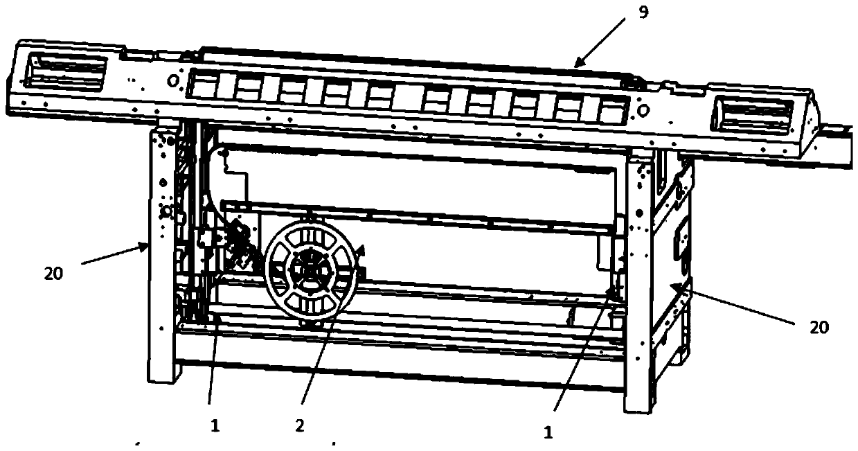
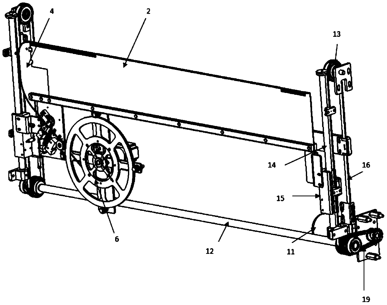
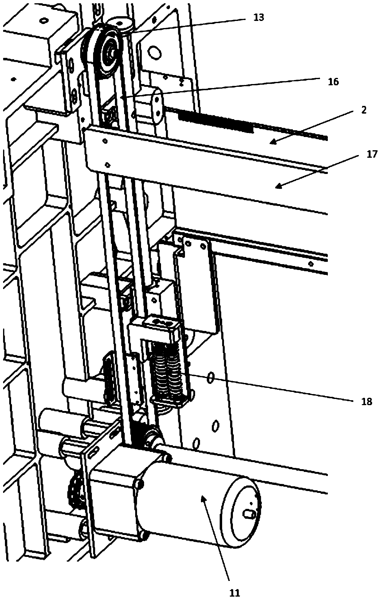
Opening device for automatic threading plate of flat knitting machine

A flat knitting machine and automatic threading technology, applied in knitting, weft knitting, textile and paper making, etc., can solve the problems of reduced work efficiency, high cost, impracticality, etc., and achieve reduced knitting cost, low manufacturing cost and convenient installation. Effect

Pending Publication Date: 2019-08-30
NINGBO CIXING
View PDF0 Cites 3 Cited by
  • Summary
  • Abstract
  • Description
  • Claims
  • Application Information

AI Technical Summary

Problems solved by technology

Since some flat knitting machines are equipped with an automatic opening device, elastic yarn is used as the opening fabric, which also produces waste yarn, and the opening device is complicated, with high failure rate and high cost.
It can be seen that before the existing flat knitting machine starts to weave, it must use the waste yarn to realize the overall weaving of the woven piece, which not only reduces the overall work efficiency, but also wastes the yarn.
[0003] Based on the above technical problems, the current situation is that it is not practical for most manufacturers and users of flat knitting machines to use the method of starting device to start the weaving piece, and they still use the original waste yarn pulling method for weaving. There is no effective plan in the industry to design and optimize the opening device of the flat knitting machine

Method used


Image

  • Opening device for automatic threading plate of flat knitting machine
  • Opening device for automatic threading plate of flat knitting machine
  • Opening device for automatic threading plate of flat knitting machine

Examples


Embodiment Construction

[0030] The present invention will be further described below in conjunction with specific examples, but the present invention is not limited to these specific implementations. Those skilled in the art will realize that the present invention covers all alternatives, modifications and equivalents as may be included within the scope of the claims.

[0031] In describing the present invention, it should be understood that the terms "center", "longitudinal", "transverse", "length", "width", "thickness", "upper", "lower", "front", " The orientations or positional relationships indicated by "rear", "left", "right", "vertical", "horizontal", "top", "bottom", "inner", "clockwise", "counterclockwise" are based on the attached The orientation or positional relationship shown in the figure is only for the convenience of describing the present invention and simplifying the description, and does not indicate or imply that the referred device or element must have a specific orientation, be c...


PUM


Abstract

The invention discloses an opening device for an automatic threading plate of a flat knitting machine. The opening device comprises left and right lifting devices, the threading plate and an opening needle. The left and right lifting devices are symmetrically arranged on left and right racks on the two sides of the flat knitting machine; the threading plate is installed on the left and right lifting devices for driving the threading plate to ascend and descend vertically, the opening needle is arranged at the top of the threading plate, a lead plate is installed at the end of one side of the threading plate, and a lead channel allowing a steel wire to penetrate and penetrating into the opening needle is arranged on the lead plate; a steel wire conveying and withdrawing device for conveyingor withdrawing a steel wire is installed below the threading plate, the tip end of the steel wire is located inside the lead channel, a steel wire limiting switch is installed in the middle of the steel wire conveying and withdrawing device, and a limiting block matched with the steel wire limiting switch for limiting is arranged on the steel wire. The steel wire automatically penetrates throughor is disengaged from the opening needle through eh steel wire conveying and withdrawing device and the lead channel, the assembling efficiency is improved, the steel wire limiting switch is arrangedfor controlling the steel wire conveying and withdrawing device to stop pushing of the steel wire, and yarn hanging and disengaging of the automatic opening device are stable.

Description

technical field [0001] The invention belongs to the technical field of flat knitting machines, in particular to an opening device for an automatic threading plate of a flat knitting machine. Background technique [0002] The flat knitting machine can complete the weaving of a complete woven piece. Generally, a complete woven piece is mainly composed of waste yarn, thread removal, opening, idling, rib, body and other parts; The pulling output process is to pull the formed knitted fabric out of the loop forming area, give the fabric a certain traction force and then send it out. The traction force has a great influence on the loop forming process and product quality. The following basic requirements should be met: Since the loop forming process is continuous If it is carried out, it should be required that the traction movement should also move continuously; the traction force acting on each coil should be stable, uniform and consistent; and the traction amount per unit time o...

Claims


Application Information

Patent Timeline
Patent Type & Authority Applications(China)
IPC IPC(8): D04B15/00
CPCD04B15/00
Inventor 肖运全胡跃勇
Owner NINGBO CIXING
Why Eureka
Try Eureka