Primary liquefier

A liquefier and head technology, applied in the field of liquefiers, can solve the problems of waste, non-flowing and slow cooling medium, etc., and achieve the effects of prolonging the residence time, enhancing the liquefaction effect, and enhancing the liquefaction effect.

Pending Publication Date: 2019-08-30
NINGBO FENGCHENG YONGSHENG BOILER CO LTD
View PDF0 Cites 3 Cited by
  • Summary
  • Abstract
  • Description
  • Claims
  • Application Information

AI Technical Summary

Problems solved by technology

[0005] However, when the cooling medium in the existing liquefier passes through the baffle, the cooling medium near the liquefier wall of the baffle does not flow or flows slowly, so that heat exchange cannot be performed well, and the gaseous material is under pressure. When

Method used


Image

  • Primary liquefier
  • Primary liquefier
  • Primary liquefier

Examples


Embodiment Construction

[0024] Specific embodiments of the present invention will be described in detail below in conjunction with the accompanying drawings. It should be understood that the specific embodiments described here are only used to illustrate and explain the present invention, and are not intended to limit the present invention.

[0025] First of all, in order to facilitate the understanding of the primary liquefier provided in the embodiment of the present application, its application scenario is firstly explained. The primary liquefier provided in the embodiment of the present application is used to prolong the condensation time of the gas material and enable the cooling water to fully exchange heat.

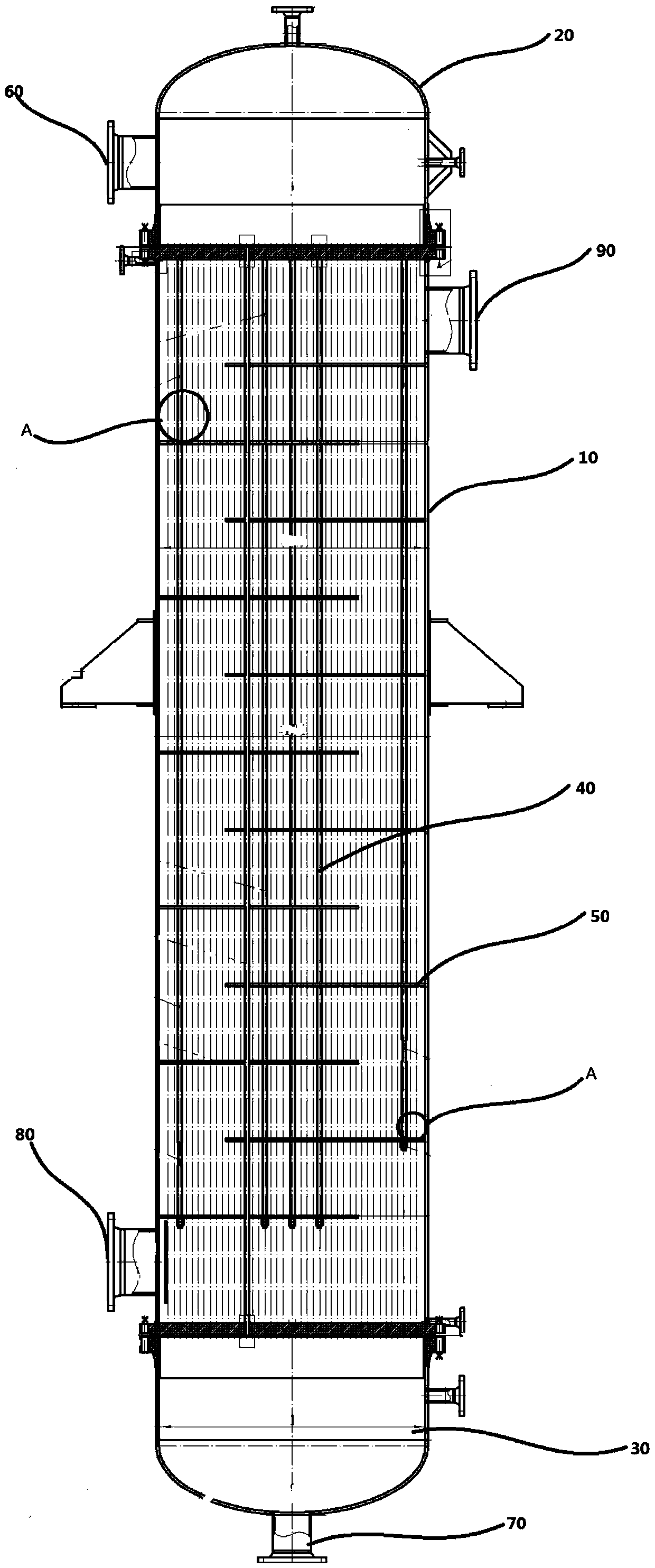
[0026] first reference figure 1 , figure 1 It is a structural schematic diagram of a liquefier in the prior art; in the prior art, a cooling medium is used to enter the interior of the main housing 10 through the cooling water inlet 80 at the bottom of the main housing 10, and flow out f...


PUM


Abstract

The invention provides a primary liquefier. The primary liquefier comprises a main housing, an upper seal head and a lower seal head, wherein an upper pipe plate and a lower pipe plate are correspondingly arranged in the upper seal head and the lower seal head in sealed and rotary mode, a pipe bundle is fixedly connected between the upper pipe plate and the lower pipe plate, a plurality of archedtraverse baffles are connected onto the pipe bundle, the plurality of arched transverse baffles are arranged at intervals in staggered mode, and all the plurality of arched transverse baffles are rotatably connected onto the inner wall of the main housing. The primary liquefier further comprises a drive assembly used for driving the upper pipe plate to rotate, and a pneumatic pressurizing assemblyarranged at the top of the upper seal head and rotating relative to the upper pipe plate, wherein the drive assembly is connected with the pneumatic pressurizing assembly through a gear device. According to the primary liquefier provided by the embodiment of the invention, duration of stay of a gaseous material in the pipe bundle is prolonged by synchronously rotating the upper pipe plate, the pipe bundle, the lower pipe plate and the arched transverse baffles, through rotation of the arched transverse baffles, dead angle-free flow heat exchange of a cooling medium is realized, the liquidation effect is enhanced, and the pipe bundle is suffused with the gaseous material through the pneumatic pressurizing assembly.

Description

[0001] Technical field: [0002] The invention relates to the technical field of liquefiers, in particular to a primary liquefier. [0003] Background technique: [0004] In the chemical industry, there are often materials that need to be liquefied, so the working efficiency of the liquefier is related to the actual production efficiency of the process to a considerable extent. [0005] However, when the cooling medium in the existing liquefier passes through the baffle, the cooling medium near the liquefier wall of the baffle does not flow or flows slowly, so that heat exchange cannot be performed well, and the gaseous material is under pressure. When pumped into the liquefier, it will be affected by the pressure and quickly pass through the tube bundle, resulting in insignificant liquefaction effect, and the insufficiently liquefied gas material will be discharged from the non-condensable gas outlet, causing unnecessary waste. [0006] Invention content: [0007] In view of...

Claims


Application Information

Patent Timeline
IPC IPC(8): F28B1/04F28B9/02F28F9/007F28F9/02F28F9/24F28F9/26
CPCF28B1/04F28B9/02F28F9/007F28F9/0219F28F9/24F28F9/26
Inventor 齐银君魏续华王龙华邵金龙任立军
Owner NINGBO FENGCHENG YONGSHENG BOILER CO LTD
Why Eureka
Try Eureka